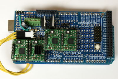
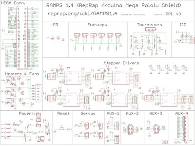
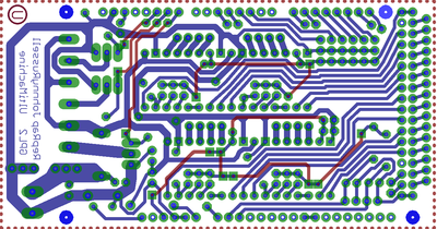
Arduino Mega Pololu Shield
Release status: Experimental
| Description | A circuit board that fits on the Arduino MEGA and holds Pololu A4983 stepper driver carrier and the rest of RepRap's electronics.
|
| License | |
| Author | |
| Contributors | |
| Based-on | |
| Categories | Electronics
|
| CAD Models | |
| External Link |
Summary
This board is a work in progress and I am trying to update this page as I find time. It is currently working as shown built on an Arduino manufactured Arduino MEGA Shield. We plan on printing it on Mendel with the marker or plastic printed on copper etch resists methods suggested by Vik. It has been designed with an eye towards being made on a RepRap. The traces are wide, with wide gaps between them where possible. We tried to use minimal vias and traces on the side needed for easy soldering to connectors. This board is mostly a copy from Adrian's Pololu_Electronics, but it was also inspired by all the other awesome RepRap contributors on the blogs, IRC, and forums - thank you guys. It is designed to fit the entire electronics needed for a RepRap in one small package for low cost. It has provisions for the cartesian robot and two extruders and a heated bed. It fits five Pololu A4983 stepper drivers, 4 mosfets for heater / fan outputs and 2 thermistor circuits.
It is designed to be printable on a Mendel :)
Description
A couple tricks that stand out are placing the Pololu boards on pin header sockets so they can be replaced easily in case of failure. Placing the Pololus up as another stacked layer allowed us to put the capacitors and pull up resistors for each stepper driver underneath it giving us much needed board space. We placed the pin headers for the stepper motor outputs on top of the Pololu boards, freeing that valuable board space and ideally reducing noise in the crowded board.
We had to modify Joaz's pin definitions to try to make this board printable. We tried to carry as many of his great ideas over as we could like putting the endstops on interrupt pins. We also hooked all the Mosfets onto PWM pins so they can hopefully be assigned to heater, fan, heated bed, or other duty. As you can see the thick traces and not having an easy way to do vias makes for a tight squeeze in some places on the board.
This board uses servo style connectors to connect to the endstops, motors, and leds. These connectors are gold plated and rated for 3A.
Instructions:
These instructions are incomplete! Make sure to check the prototype shield you use for pin holes that have traces tying them together. You most likely will have to cut some traces to keep from shorting circuits together that do not belong. The board used Arduino Mega shield pictured here is the one manufactured by Arduino. I only had to cut traces in about 4 places and it only took a couple seconds each with the little grinding bit on a dremel tool(I will add a picture showing where to cut traces on this board soon).
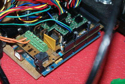
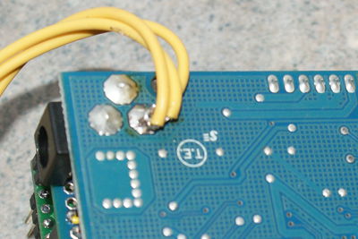
There are a few options for powering the board. Pictured I have slightly modified the Arduino Mega board to use it's power jack to feed 12V to the RepRap Shield. If you are considering this method make sure to check your power supply's output voltage first. The maximum recommended input voltage for the Arduino Mega board is 12v, Higher voltage can be unhealthy for your Arduino and waste energy. The main indicator of having too high of voltage will be the voltage regulator getting hot, continued abuse will result in the release of all of it's magic smoke and failure to operate. I used desolder wick to remove the solder from the + pin on the Mega's power jack. I then fished the three wires through the board around the now mostly loose pin and soldered it back. These wires are then hooked to the three 12V+IN pins on the shield. Other more safe power method involves hooking the three 12V+IN and three GND pins to a XLR jack like in Mendel spec, or adding a power jack directly to the shield.
To Do:
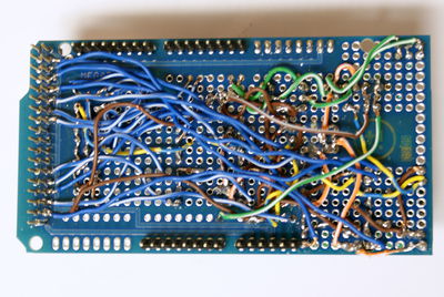
PRINT BOARD. The wiring for the back of the shield is quite tedious and error prone. Modifications to Arduino Mega may not be preferred for everybody.The voltage regulator on the Mega board does not like voltages higher than 12v, my power supply's voltage of 12.6v gets it pretty hot.
Source
File:ArduinoMegaPololuShield.zip
New Pin Assignments:
This is the code under "pins.h" associated with the shield.
<source>
- elif MOTHERBOARD == 3
- define USE_EXTRUDER_CONTROLLER false
- define X_STEP_PIN (byte)24
- define X_DIR_PIN (byte)26
- define X_MIN_PIN (byte)3
- define X_MAX_PIN (byte)2
- define X_ENABLE_PIN (byte)22
- define Y_STEP_PIN (byte)28
- define Y_DIR_PIN (byte)30
- define Y_MIN_PIN (byte)18
- define Y_MAX_PIN (byte)19
- define Y_ENABLE_PIN (byte)52
- define Z_STEP_PIN (byte)48
- define Z_DIR_PIN (byte)50
- define Z_MIN_PIN (byte)20
- define Z_MAX_PIN (byte)21
- define Z_ENABLE_PIN (byte)46
- define BASE_HEATER_PIN (byte)-1
- define POWER_SUPPLY_PIN (byte)-1
//extruder pins
- define EXTRUDER_0_MOTOR_SPEED_PIN (byte)32
- define EXTRUDER_0_MOTOR_DIR_PIN (byte)34
- define EXTRUDER_0_HEATER_PIN (byte)7
- define EXTRUDER_0_FAN_PIN (byte)-1
- define EXTRUDER_0_TEMPERATURE_PIN (byte)0 // 57 Analogue input 3
- define EXTRUDER_0_VALVE_DIR_PIN (byte)-1
- define EXTRUDER_0_VALVE_ENABLE_PIN (byte)-1 // Valve needs to be redesigned not to need this
- define EXTRUDER_0_STEP_ENABLE_PIN (signed int)-1
- define EXTRUDER_0_LOW_HEAT (byte)110
- define EXTRUDER_0_HIGH_HEAT (byte)255
- define EXTRUDER_1_MOTOR_SPEED_PIN (byte)-1
- define EXTRUDER_1_MOTOR_DIR_PIN (byte)-1
- define EXTRUDER_1_HEATER_PIN (byte)-1
- define EXTRUDER_1_FAN_PIN (byte)-1
- define EXTRUDER_1_TEMPERATURE_PIN (byte)-1 // Analogue input
- define EXTRUDER_1_VALVE_DIR_PIN (byte)-1
- define EXTRUDER_1_VALVE_ENABLE_PIN (byte)-1 // Valve needs to be redesigned not to need this
- define EXTRUDER_1_STEP_ENABLE_PIN (signed int)-1 // 7 - Conflicts with the fan; set -ve if no stepper
- define EXTRUDER_1_LOW_HEAT (byte)64
- define EXTRUDER_1_HIGH_HEAT (byte)255
</source>

