Adrians Prusa Notes
Release status: experimental
| Description | How Adrian builds a Prusa Mendel.
|
| License | GPL
|
| Author | |
| Contributors | |
| Based-on | |
| Categories | Prusa Development
|
| CAD Models | |
| External Link |
Introduction
This is my page of notes on how I put together a Prusa Mendel. These are not so much improvements, but more modifications and options done for both personal convenience and the convenience of RepRap Ltd, as this is the one we sell. I have documented them here as others may find them helpful.
This page is intended to be read in conjunction with the main RepRap page on Prusa Mendel Assembly here and the Prusa Visual Assembly Guide. It is a good idea to read both of these because the guide is beautifully clear, but the wiki assembly instructions are easier to correct and enhance, and so tend to be slightly more up-to-date.
The files needed for what's here are in my fork of the Prusa Mendel Git repository here: https://github.com/AdrianBowyer/PrusaMendel in the directory AdriansPrusaModifications.
Configuration
The main components I use in my version of Prusa Mendel are:
- Sanguinololu electronics,
- Aluminium heated bed,
- My Universal mini extruder, and
- XBox 360 203 watt power supply.
I also use some modified printed parts and a few extra ones. All this is described and linked to in the sections below.
Mechanics
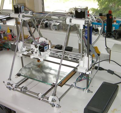
The most significant difference between my version of Prusa Mendel and the standard one is that I reverse the X axis. Looking at the front of the machine with the Y motor at the back, the X motor is on the left, not the right. This allows easier wire layouts, and - in particular - allows neat connection of the wiring to both the X axis and the heated bed by cable-tying it along lengths of 3mm filament for support.
I have also made a number of minor mechanical alterations that are listed in the next section.
Altered reprapped parts
endstop-holder.scad
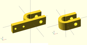
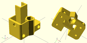
The endstop holder is the left hand image. It holds a microswitch with 9.5mm mounting centres and M2.5x12 mounting screws. Get a microswitch with just a button, not the lever as well - it's more accurate.
If you set the variable pcb_mount=true; in the OpenSCAD file it also generates a PCB holder (right image) to allow you to mount the RepRap control electronics on the machine using M3 screws. See below.
pla-bushings-4.scad
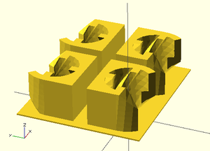
If you have all 12 PLA bushings in an array as a single STL file it makes arranging them in a build less versatile as you can't cram them into small spaces. Arranging them one at a time gives a lot of versatility, but they are so delicate that they can detach, even from a well-heated bed.
My compromise it to have four on their own raft. This prints reliably, and is easy to slide about between other parts to print wherever you want. Print three of these to get 12, obviously. The raft is thin enough to cut from the finished parts easily with a scalpel. Mind your fingers...
x-end-idler.scad
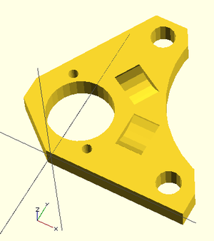
I have replaced the unsupported bridges with thin webs (left picture), which both print more cleanly and are stronger. The M8 nut cavity now has a hole through for the M8 threaded rod, and a 45o conical base to the barrier that rests on the nut (right picture). This again prints more cleanly.
x-end-motor.scad
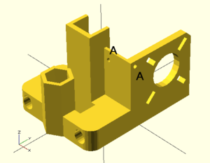
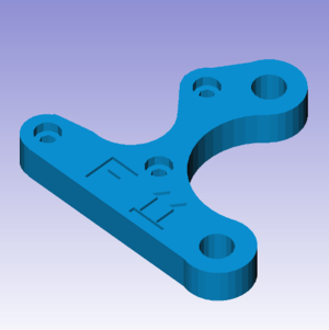
This has the same webs and cone as above. In addition there are two small holes (A A) that allow a 3mm diameter length of filament to be attached using a cable tie to run the X-axis wiring.
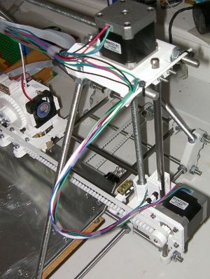
The picture on the right shows the idea, though that was taken with the old design. A 430mm length of 3mm PLA filament is held to the top of the Prusa Mendel beside the Z motor by two cable ties round the threaded rods. It loops through the hole on the right in the OpenSCAD picture and a third cable tie through the hole on the left secures it.
The wires are shown taped here, before they are cable-tied. This is generally a good idea: attach all wires with sticky tape first, then, only when everyting is in place and you're happy with the layout, go round putting the cable ties on and cutting off the tape.
xlr-bracket.scad
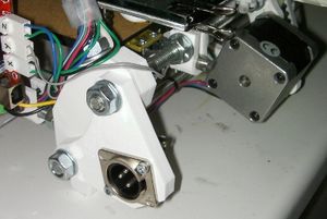
This fits on the frame vertex to the left of the Y motor viewed from the back of the Prusa Mendel. It holds a standard RepRap 3-pin XLR plug power connector. Remember to leave the 8mm threaded rods sticking out enough to hold it.
See the power supply section below for wiring details.
ybrac-t.scad
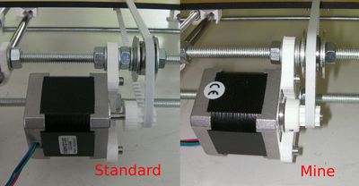
This modification of the standard Y motor bracket has slots rather than holes. This allows it to be fitted to the Prusa Mendel and taken off without taking anything else apart.
The motor has also been rotated about its axis to move one of its mounting screws away from the Y belt pulley. This allows the pulley mounting to be simpler (see the photo), and the toothed drive to sit nearer the motor, thereby reducing the bending moment on the shaft and the forces on the motor bearings.
I leave out the nut between the motor mount and the mudguard washer before the bearing, and just have three washers there.
Y belt clamp
If you use 10mm thick MDF (or similar) for the Y bed lower component then ignore this section.
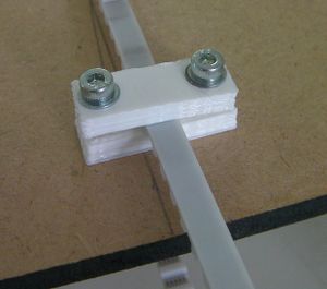
But I use 6mm MDF, which makes the Y belt run slightly out of line. Fix this simply by printing out two extra Y belt clamps (which are 4mm thick) and putting them under the belt.
Heated Bed
Bill of Materials
| Item | Source | No. off |
| 3mm thick Aluminium sheet 230mm x 230mm | http://stores.ebay.co.uk/Forward-Metals-Ltd/_i.html?_fsub=17853190 | 1 |
| Glass bed | Glass cutter | 1 |
| 12 ohm cased resistors | Mouser 284-HS15-12F | 9 |
| MOSFET mounting kit | RS 7073361 | 1 |
| MOSFET | RS 7165558 | 1 |
| 10K Thermistor | RS 4840149 | 1 |
| Bed springs | Lee Springs LC 047E 06M | 4 |
| M3x30 cs | RS 4829221 | 4 |
| M3 x20 cs | RS 553419 | 4 |
| M3 nylock nuts | 4 | |
| M3 nuts | 6 | |
| M3 x 6 cs | RS 553396 | 20 |
| tmnl block (3) | 1 | |
| stripbd 10x13 | 1 | |
| 3 way pin header | RS 4838477 | 1 |
| 3 way header shell | 1 | |
| crimp connectors | 3 | |
| LED | 1 | |
| 1k resistor | 1 | |
| foldback clips | Stationers | 4 |
| 1.2 m 20A wire | 1 |
Circuit diagram
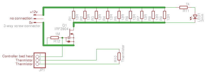
The bed has 9 12 ohm resistors in parallel, giving an overall resistance of 1.333 ohms, which in turn gives 108 watts of heat at 12v. These resistors should be panel mounting high-power types with an aluminium jacket and mounting holes.
The IRF2804 MOSFET is a cheap, but truly amazing, device. It will switch almost 300A (rather over-rated for this application, but why not), and has an on resistance of only 0.0023 ohms.
The main power connector is an ordinary "chocolate block" 3-way screw strip. The central hole is not electrically connected, but is used mechanically - see below.
Use very fat wire to connect all the above components - it has to take high current.
R11 and the LED in parallel with the heater resistors are an indicator which tells you when the heater is on.
In addition there is a 3-way pin header that turns the MOSFET on and off, and that returns the resistance from the thermistor thermometer.
Construction
Clamp the MDF Y bed symmetrically in the middle of the aluminium sheet, and use it as a template to drill four 3mm mounting holes. Countersink them on the top side. The long countersunk screws will go through these holes, with springs between the MDF and the aluminium. This allows you to adjust the heights of the four corners to get the bed exactly parallel with the X and Y movement of the Prusa Mendel. Use nylock nuts on the countersunk screws so the adjustment doesn't drift.
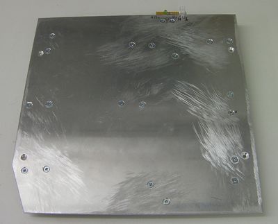
In the corner that will be at X=0, Y=0 cut an angled corner off the aluminium bed to match the glass plate (see below). This will allow the extruder to be purged without building a messy pike on the plate before a build - the extrudate will fall through the hole.
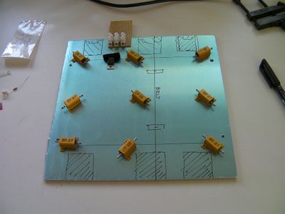
Now to decide where not to attach things. Put the MDF back on the machine and temporarily assemble the bed (no need to put the nuts on the screws). Move the bed to and fro, and work out regions where anything bolted under the aluminium may collide with, for example, the Y belt bearings or the Y smooth bar clamps, and the screws and springs. Block these regions out with a felt pen.
Now position the heater resistors, the transistor, and the screw connector where they won't hit anything. Try to space the resistors evenly to get even heating. The stripboard goes right under the screw connector (copper away from the aluminium) and pokes out the back. It's for mounting the LED and the pin header connector.
Mark the mounting holes of everything with the felt pen and drill them all 3mm, countersinking the other sides.
The holes in the resistor tabs are smaller than 3mm. But they are just right for tapping 3mm. Tap all the mounting holes in the resistors with an M3 taper tap, taking care to keep it at right angles to the resistor body.
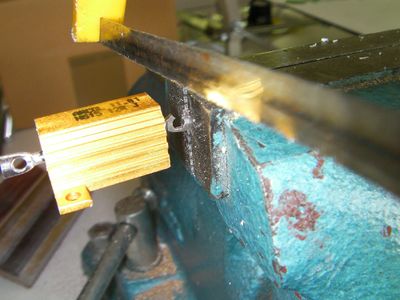
Now use a hacksaw to cut slots in the wire hole on the two leads of each resistor. This will allow you to slot connector wire in from the top (when being made; bottom when installed). This is much easier than trying to thread it through the holes. The easiest way to cut the slots is to put the tips of the leads in a vice with the resistor projecting to one side of it.
Use the 6mm countersunk screws to mount the resistors to the plate. You may care to put silicone heat-sink compound under them to get good thermal contact.
Use 12mm M3 countersunk screws to attach the transistor with its mounting kit (which insulates it from the aluminium), and to attach the screw strip and stripboard.
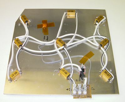
Wire everything up according to the circuit diagram.
Use Kapton tape to hold things down. The cross is the thermistor - put it well away from the heating resistors near the middle. I put a pad of cotton wool under it to insulate it and to keep its temperature close to that of the aluminium.
Nothing should be electrically shorted to the aluminium - check this with a meter.
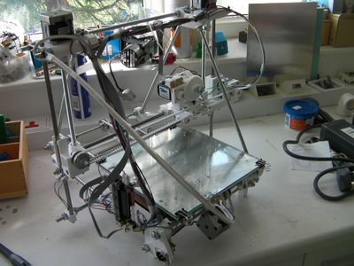
Here's the finished bed fitted and viewed from the back of the machine. The countersinking should obviously put the screw heads below the plane of the top of the bed - the glass plate has to sit flat on top of it.
The glass plate is held down by the four foldback clips.
The extruder is parked at x=0, y=0. This places it over the cut-out corner of the bed.
As you can see, the machine's wiring is not finished in this picture. But the loop extending towards the camera carries the power and signal connection to the heated bed. A loop of 3mm PLA filament 640 mm long is attached to the top of the machine next to the Z motor by two cable ties. The other end of it is clamped in the central unused slot in the heated bed's screw connector. Two fat wires run the 12v supply from the power connector bottom left of the picture, and three tin wires run the on/off signal from the control electronics to the gate of the MOSFET and the connections to the thermistor.
