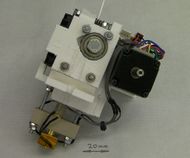
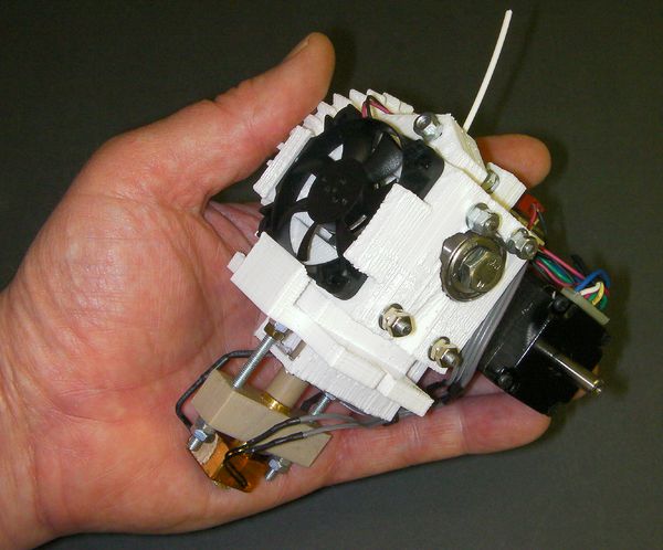
RepRap Universal Mini Extruder
Release status: experimental
| Description | A small extruder for 1.75mm filament.
|
| License | GPL
|
| Author | |
| Contributors | |
| Based-on | [[]]
|
| Categories | |
| CAD Models | |
| External Link |
Introduction
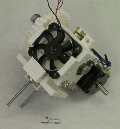
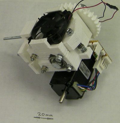
This printable extruder is intended to work on RepRap Mendel, RepRap Huxley, and virtually any other open-source 3D printer you can find.
It features:
- 1.75 mm filament
- Adaptable mounting plate to attach it to virtually any 3D printer
- Very compact high-torque NEMA 11 motor
- Active ducted cooling for high reliability
- Wade-style hobbed bolt filament transport
- Wing-nut drive to spread the torque loading on the plastic gears
- Push-fit hot-end parts - no thread cutting
- Easily replaced PTFE liner for the hot end
- A single M3-threaded rod cut to lengths makes all the fixings
- Lightweight: 420g (about 60% the weight of this extruder)
- Compact design (110 mm x 90 mm x 80 mm)
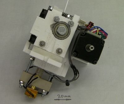
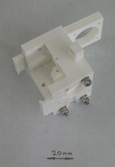
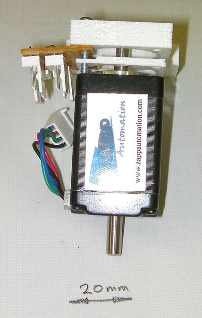
Front view
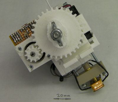
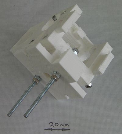
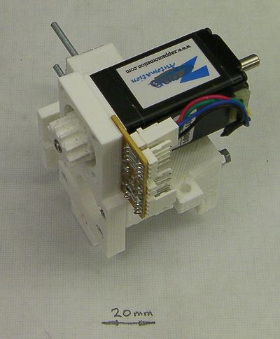
Rear view
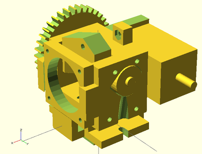
OpenSCAD design.
Bill of materials
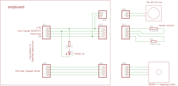
All the design files for the extruder are here in the repository. The OpenSCAD models are in the file universal-1.75mm-filament-extruder.scad, the (very simple) Eagle circuit diagram is in Design-drawings/extruder.sch and the drawings of the hot-end components are in Design-drawings/hot-end.dxf.
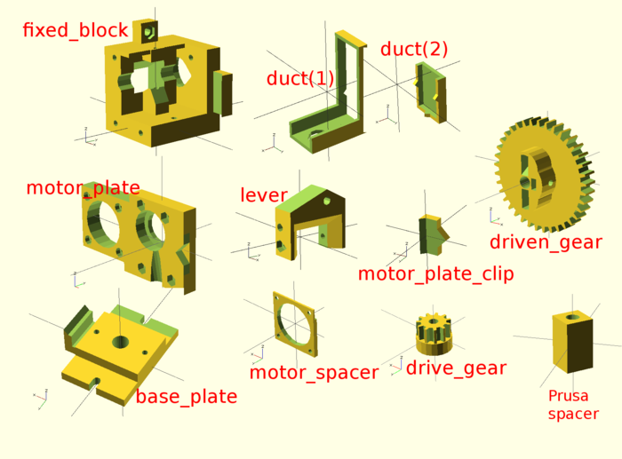
Here is the OpenSCAD rendering of the reprapped components. You will need one each of the above.
The base-plate design shown above is for Mendel (both standard and Prusa). It is easy to adapt for virtually any RepRap and RepRap-like machine, though. The only critical things from the extruder's perspective are the 8.5mm hole for the PEEK insulator, the two 3mm holes 28 mm apart for the tie-rods that retain the hot end, and the support clip for the fan. As long as those are in the right place, just about all the rest of the plate can be anywhere, with fixing holes wherever you like.
- Complete BoM here.
A useful tool
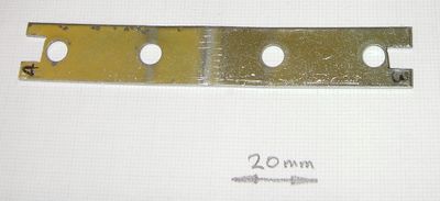
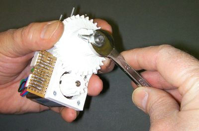
Most of the nuts in this design are in pairs as double lock-nuts. You will need spanners, of course. But most spanners are thicker than the nuts they fit. You may find it useful to get an old bit of sheet steel and cut your own spanner with a hacksaw. I used a straightened-out shelf bracket - M3 nut size at one end, M4 at the other. For this extruder you only need the M3.
The hot end
Start by building the hot end.
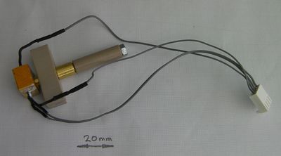
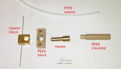
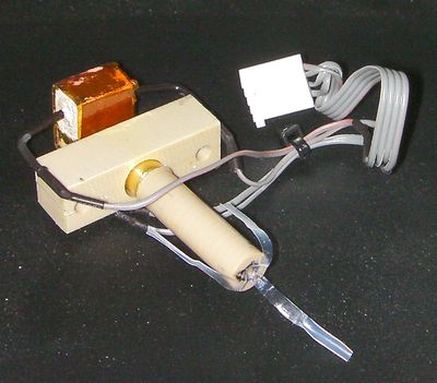
The hot end has a brass nozzle with a brass heater block containing a 6.8 ohm heating resistor and a temperature sensing thermistor. The brass nozzle has a PEEK insulator inserted into its top, and a PEEK block. The block has two M3 threaded rods running through it. These attach the hot end to the rest of the extruder. A thin PTFE liner runs down the central hole in the device, stopping about 12 mm from the bottom. The last section has no liner so that heat can conduct into the polymer more quickly.
Here is a picture of the hot-end components, and...
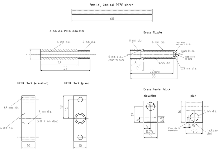
... here are the drawings for them. You could almost certainly make the nozzle and block from aluminium rather than brass. But don't use two different metals: if you do thermal expansion will cause the heater block to work lose.
Start by making the PEEK block. This is pretty straightforward. To get the 7mm deep hole, I just mark 7 mm on the side of the drill flutes with a felt-tipped pen. That is, 7mm in from the point of the tip. Make sure you can see your mark when the drill spins...
You will see that the holes for the threaded rods are 3.5 mm in diameter, even though the rods are M3. You want them to be a lose fit.
Next make the heater block. I hacksawed this roughly from a 3/8" sheet of brass, which is 9.5mm thick, not 10. Then I filed it square and drilled the holes. Clamp the block in the drill vice and support it underneath with a sacrificial piece of wood - you don't want it twisting as you drill it. None of the dimensions are critical. Make the hacksaw split on the 6mm hole last of all, and file away any burrs from the edges.
Next turn the nozzle. Face off the ends, then mark the centre with the finest centre drill you can find. Drill the 0.5mm nozzle hole about 4 mm deep. Use a woodpecker cycle - every 0.5 mm or so withdraw the drill to clear the swarf. Thake real care drilling this hole. ).5mm drills are not strong...
Turn the cone on the end. Take this just far enough back to obliterate the centre-drill mark you made. Run a fine file over the outer edge of the cone to round it off. You will probably find that you have also obliterated the end of your 0.5mm hole. Open it up again by hand with the 0.5mm drill held in a pin chuck.
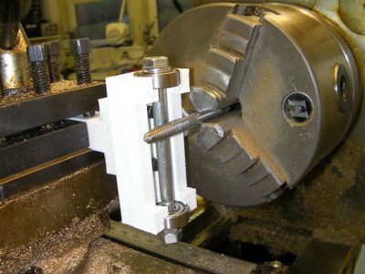
Turn down the 6mm shaft. As you near the right diameter keep stopping and check it repeatedly against the 6mm hole in the heater block. You want an interference fit - don't go to far.
Turn the nozzle round in the chuck, so it is held by that 6mm shaft. Turn down the 8mm end.
Mark the centre and drill the 6mm counterbored hole with an ordinary twist drill 8 mm deep.
Drill the 2.5mm hole about 10 mm deeper - not all the way to the end.
If you have a 6mm slot drill, you can use that to finish the counterbore. If not, grind an old 6mm drill flat as described here and use that.
Take the nozzle out of the chuck and hold the 2.5mm drill beside it. By eye line the tip up so that it's about 0.5mm in from the nozzle tip. Mark the drill at the other end with a felt-tip to coincide with the end of the 8mm section. Beware parallax. Look at what you have done, and make sure you remember the relation between your mark and where the drill will have to sink to. Put the drill in the tailstock and carefully drill to your mark. You will probably find that this has again blocked the 0.5mm hole. Holding the nozzle tip upwards (you want swarf to fall out of the big end) clear it by hand, as before. Twist a big drill by hand against the 6mm hole to chamfer the edge, again with the tip pointing up.
Finally make the PEEK insulator. Again, when turning the 6mm section, check it repeatedly against the 6mm hole in the nozzle. You want a tight fit that you can just push by hand. PEEK gets very hot with friction when machined, especially when drilled. Again use a woodpecker cycle for the 2.5mm hole, and give the drill and the PEEK plenty of time to cool between drilling.
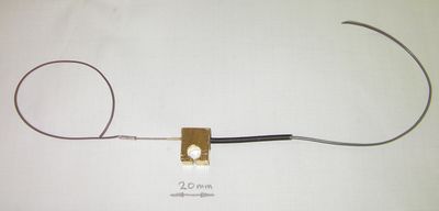
Retain the resistor inside the heater block with fire cement or high temperature epoxy. Make sure that whatever you use is rated up to 250o C. Don't cut the resistor leads - leave them full length. Crimp wires onto the ends of the resistor leads using bootace ferrules or similar (shown left). Don't solder the wires - the solder won't stand the temperature.
Put heat shrink over the join (shown right). If you do this while the fire cement or epoxy are still unset, you can push the heatshrink a little way into it. When the fixative is set and the heatshrink shrinks, this will make a very neat join. Don't bother to heat the heatshrink - when you operate the nozzle the heat will do this for you.
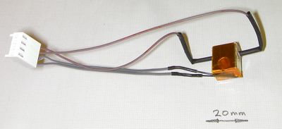
solder two leads onto the thermistor. I put PTFE sleeving taken from PTFE-insulated wire on the thermistor leads themselves. If you do this, only take one leg's insulation right up to the thermistor; leave the other short by about 3 mm. If both pieces of insulation abut the thermistor, they will put a strain on its leads as they are a little to thick to fit in the gap.
Wrap a 10mm square of PTFE plumber's tape round the thermistor itself, then insert it in its hole.
Secure it with Kapton tape wrapped round the block as shown. The tape runs right over the hole down which the nozzle will fit.
Cut the discs of tape from that hole with a scalpel.
Put the PEEK block on the brass nozzle, and then put on the heater block. If need be, stand the heater block on a short length of tube (15 mm plumbing pipe works well) and tap the nozzle through it with a soft hammer. You want a tight fit for good thermal contact. The tube is to stop the point of the nozzle getting damaged.
Push the PEEK insulator into the back, then gently push the PTFE sleeve down the device as far as it will go. Withdraw it about 10 mm and make a mark with a felt-tip pen where it enters the PEEK insulator. Withdraw it fully, match up your mark, and make sure that the liner has gone down to about 10 mm from the tip of the nozzle. Cut it to length about 20mm above your mark. Put it back in up to the mark.
Now, using a very sharp blade, split the end in three down to the mark, like three petals. Fold these back and down the outside of the PEEK insulator.
When you assemble the device, these petals will be trapped between the extruder drive body and the PEEK insulator. This holds the PTFE in place.
Assembly
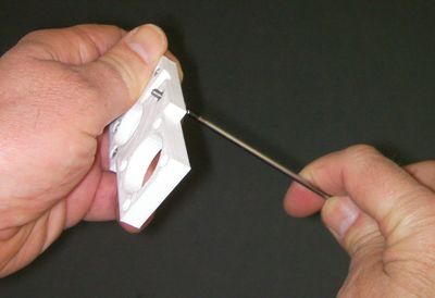
Sink four M3 nuts in the holes in the motor plate. Use a short M3 screw and washer to pull them into place. Make sure the hexagons line up before you pull.
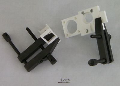
Offer up the clip to the motor plate, and the two halves of the duct to each other. Trim away any excess plastic with a blade to ensure a snug fit.
Arrange a couple of clamps to hold the parts while they set, glue them with superglue, and clamp them. The triangular lip of the clip points away from the nuts you just fitted in the motor plate.
A piece of polythene plastic bag under the clamps will ensure that they don't glue to the work...
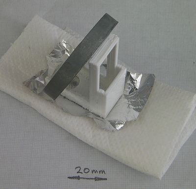
When the duct is set, glue aluminium kitchen foil onto the bottom of it. Weight it onto something soft to get the foil well pushed against the duct. The aluminium is a heat reflector. Cold air will be running on the interior of the duct, and the foil helps keep the whole thing cool from both the extruder hot end under it, and any heated bed that you may be using. When the glue is set, trim the foil round the edges and from the holes.
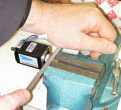
If your NEMA 11 motor has a round shaft, file a flat on it. Put Blu-tack into the gap between the motor shaft and the motor body to keep filings out of the motor's bearing. Fit the drive gear on the shaft so that the ends coincide, and note roughly where the flat needs to be. Take the gear off. Clamp the shaft (not the motor body) in a vice and file the flat. If you use a small file you can see when the flat is parallel with the shaft axis - it makes a rectangle. A trapezium means you've filed at an angle.
<videoflash type="vimeo">22485769</videoflash>
