RepRap Universal Mini Extruder
Release status: experimental
| Description | A small extruder for 1.75mm filament.
|
| License | GPL
|
| Author | |
| Contributors | |
| Based-on | [[]]
|
| Categories | |
| CAD Models | |
| External Link |
Introduction
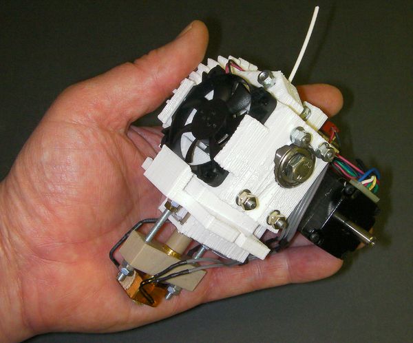
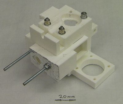
This printable extruder is intended to work on RepRap Mendel, RepRap Huxley, and virtually any other open-source 3D printer you can find.
It features:
- 1.75 mm filament
- Adaptable mounting plate to attach it to virtually any 3D printer
- Very compact high-torque NEMA 11 motor
- Active ducted cooling for high reliability
- Wade-style hobbed bolt filament transport
- Wing-nut drive to spread the torque loading on the plastic gears
- Push-fit hot-end parts - no thread cutting
- Easily replaced PTFE liner for the hot end
- A single M3-threaded rod cut to lengths makes all the fixings
- Lightweight: 420g (about 60% the weight of this extruder)
- Compact design (110 mm x 90 mm x 80 mm)
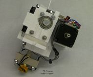
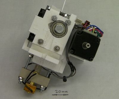
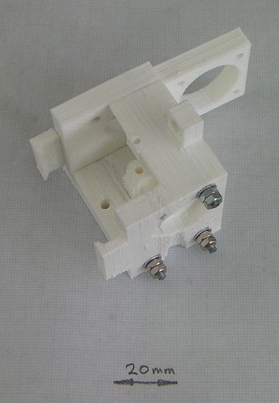
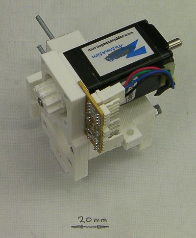
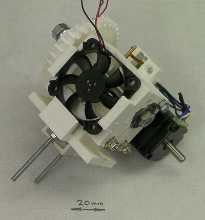
Front view
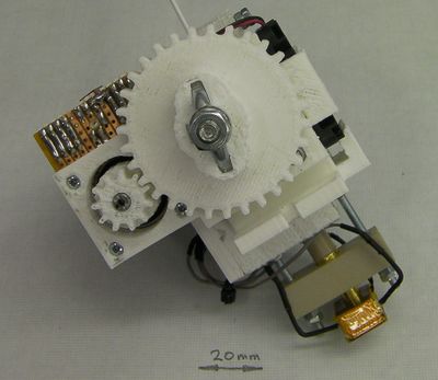
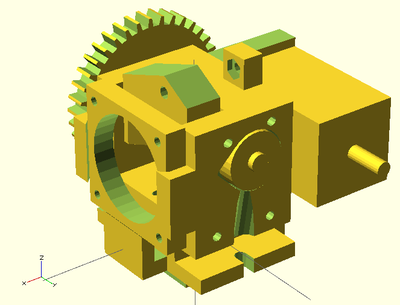
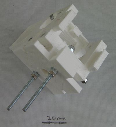
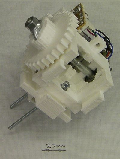
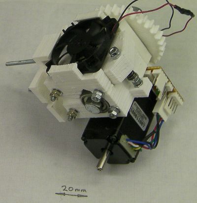
Rear view
OpenSCAD design.
Bill of materials
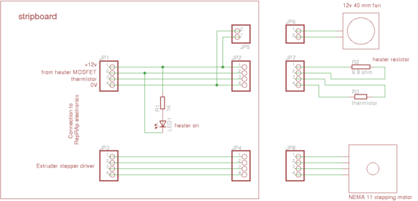
All the design files for the extruder are here in the repository. The OpenSCAD models are in the file universal-1.75mm-filament-extruder.scad, the (very simple) Eagle circuit diagram is in Design-drawings/extruder.sch and the drawings of the hot-end components are in Design-drawings/hot-end.dxf.
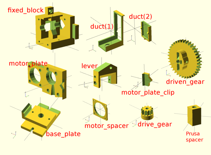
Here is the OpenSCAD rendering of the reprapped components. You will need one each of the above.
The base-plate design is for Mendel. It is easy to adapt for virtually any RepRap and RepRap-like machine, though. The only critical things from the extruder's perspective are the 8.5mm hole for the PEEK insulator, the two 3mm holes 28 mm apart for the tie-rods that retain the hot end, and the support clip for the fan. As long as those are in the right place, just about all the rest of the plate can be anywhere, with fixing holes wherever you like.
- Complete BoM here.
A useful tool
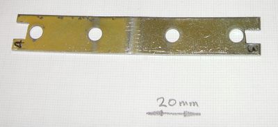
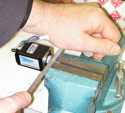
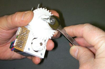
Most of the nuts in this design are in pairs as double lock-nuts. You will need spanners, of course. But most spanners are thicker than the nuts they fit. You may find it useful to get an old bit of sheet steel and cut your own spanner with a hacksaw. I used a straightened-out shelf bracket - M3 nut size at one end, M4 at the other. For this extruder you only need the M3.
The hot end
Start by building the hot end.
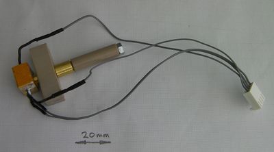
The hot end has a brass nozzle with a brass heater block containing a 6.8 ohm heating resistor and a temperature sensing thermistor. The brass nozzle has a PEEK insulator inserted into its top, and a PEEK block. The block has two M3 threaded rods running through it. These attach the hot end to the rest of the extruder. A thin PTFE liner runs down the central hole in the device, stopping about 12 mm from the bottom. The last section has no liner so that heat can conduct into the polymer more quickly.
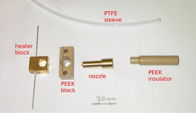
Here is a picture of the hot-end components, and...
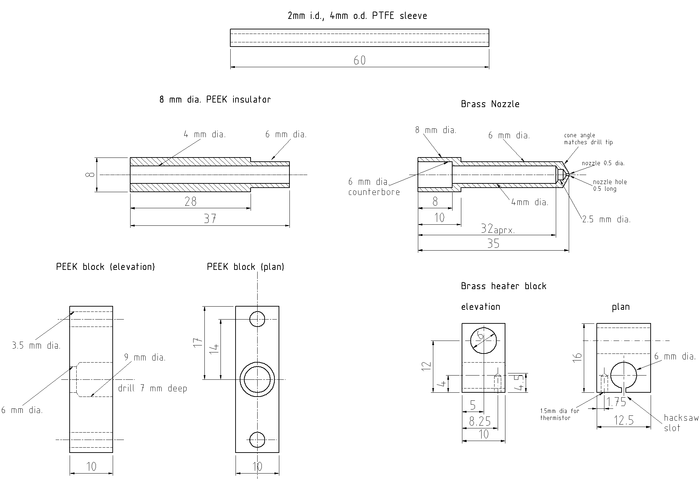
... here are the drawings for them. You could almost certainly make the nozzle and block from aluminium rather than brass. But don't use two different metals: if you do thermal expansion will cause the heater block to work lose.
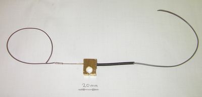
Retain the resistor inside the heater block with fire cement or high temperature epoxy. Make sure that whatever you use is rated up to 250o C. Don't cut the resistor leads - leave them full length. Crimp wires onto the ends of the resistor leads using bootace ferrules or similar (shown left). Don't solder the wires - the solder won't stand the temperature.
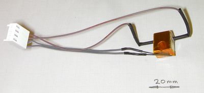
Put heat shrink over the join (shown right). If you do this while the fire cement or epoxy are still unset, you can push the heatshrink a little way into it. When the fixative is set and the heatshrink shrinks, this will make a very neat join. Don't bother to heat the heatshrink - when you operate the nozzle the heat will do this for you.
solder two leads onto the thermistor. I put PTFE sleeving taken from PTFE-insulated wire on the thermistor leads themselves.
Assembly
<videoflash type="vimeo">20596031</videoflash>
