ScrewRap
This page is a development stub. Please enhance this page by adding information, cad files, nice big images, and well structured data!
Release status: Experimental

| Description | T-Slot reprap using leadscrews instead of belts
|
| License | unknown
|
| Author | |
| Contributors | |
| Based-on | |
| Categories | |
| CAD Models | |
| External Link |
Contents
Design Goals
The following list summarise what the ScrewRap hopes to achieve:
- Minimal tools. I want assembly to be as easy as possible. The tools I'm thinking of are Allen (hex) keys, screwdrivers and maybe a drill. This list may increase as time goes on, but not by much.
- Cheap. Even though I'm using leadscrews, I still want the rest of the printer to be as cheap as possible.
- Accurate. To achieve this the design requires a sturdy frame and precise linear motion components.
- Easy to source. I want to avoid custom made parts as much as possible, and use standard parts such as T-Slot, Stepper motors, Bearings etc. Where specialised components are required they will be 3D printed. The leadscrews may be slightly more difficult in sourcing than the rest.
Specification
- Printed Parts: 37
- Non-Printed Parts: >88
- Material Cost: ?
- Cost: ?
- Printing Size: 250mm x 260mm x 280mm
- Resolution : XY = 6.25μm with 20mm pitch leadscrew; Z = 0.625μm with 2mm pitch leadscrew (1/16th microstepping assumed)
- Accuracy : <0.1mm / 300mm
- Speed: up to 1000mm/s. This is a calculated guess until I can prove it.
Parts list
Printed parts
All STL files can be found on the ScrewRap GitHub Repository.
| Part | Description | Quantity |
|---|---|---|
| Top left support | 1 | |
| Top right support | 1 | |
| Z motor mount | 2 | |
| Bearing holder | Holder for the Pillow bearings (or "skate" bearings) on all the axis motors | 4 |
| Gantry brace | 2 | |
| Z clamp | Clamp for the bottom of the Z smooth rod. Also includes opposite gantry brace | 2 |
| Foot | 4 | |
| Frame Brace | Corner braces for the lower frame | 4 |
| Y clamp | Clamp for the Y smooth rods | 4 |
| Y motor mount | 1 | |
| Y bearing block | Holder for the Y axis pillow bearing. | 1 |
| Y bearing holder | Holder for the Y axis linear bearings | 3 |
| Y leadscrew nut holder | 1 | |
| X end motor | 1 | |
| X end idler | 1 | |
| Z linear bearing clamp | 2 | |
| Quickfit extruder | The Quickfit Extruder by RichRap | 1 |
| Quickfit part A | The half of the quickfit mount with the leadscrew nut mount | 1 |
| Quickfit part B | The other half of the quickfit mount | 1 |
Non-printed parts
TODO: Complete this table
| Part | Quantity | Description | Possible suppliers (Feel free to add to this list) |
|---|---|---|---|
| 440mm 20x20 aluminium extrusion | 2 | 20x20mm aluminium extrusion with a 6mm slot | KJN Aluminium Profiles (UK) |
| 430mm 20x20 aluminium extrusion | 2 | ||
| 390mm 20x20 aluminium extrusion | 3 | ||
| 440x10mm ground rod | 2 | This is the smooth rod for the linear bearings to travel along | Zapp Automation (UK) |
| 430x10mm ground rod | 2 | ||
| 510x10mm ground rod | 2 | ||
| LM10UU Linear bearings | 12 | I bought 4 bearings for each axis. You could get away with 3 bearings for the Y axis. | Zapp Automation (UK) |
| M4x10mm hex screws | 62 | These are to hold parts to the aluminium extrusion. I bought a pack of 100 to give a few spares |
Development
Here's a wall of photos showing the development of project. The top ones are newest.
Z rods now installed
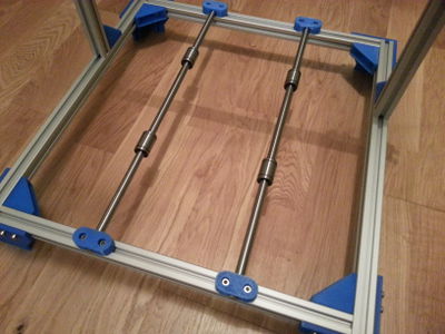
Y rods installed. Tried out the Cura slicer with the mounts. Some of the parts had poor infill on the last layers, although thankfully it's only cosmetic.
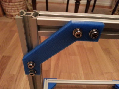
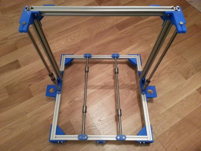
Gantry braces now added
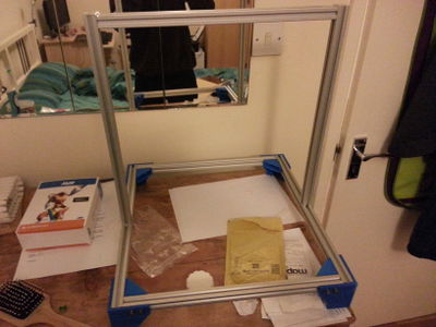
A mockup of the frame with the gantry taped together
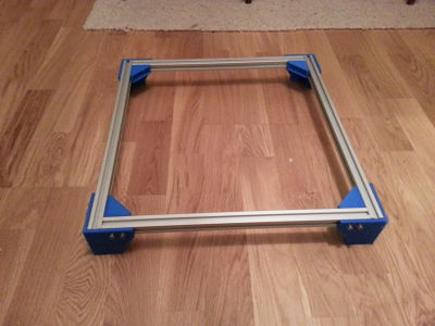
Early progress assembling the base.
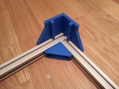
The foot design for the screwrap
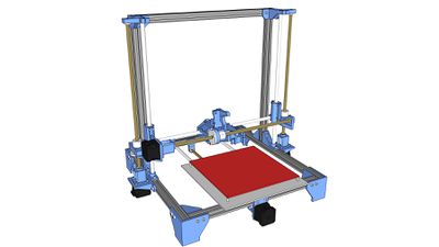
Overview of the ScrewRap design


Inspiration
The following list contains all the sources I've found inspiration or parts for this design (Currently incomplete):
- smartroad's Dual-Struder Fabricator. This is the foundation for my design, with everything else being built on top
- Jspark's Kid Mendel has the option to use leadscrews for all axes. He's also used threadless ballscrews which I may investigate in the future as a cheaper alternative.
- MendelMax Minimal Y Rod Mount by cobra18t. My Y mounts are very similar to these.