LongboatPrusa
Release status: Working

| Description | LM8UU Liner Bearing
Based Prusa.
|
| License | GPL
|
| Author | |
| Contributors | |
| Based-on | |
| Categories | Mendel Variations
|
| CAD Models | Coming soon.
|
| External Link |
The Longboat Prusa, is a Prusa Mendel variant which uses LM8UU liner bearings on all axis’s. It has a 4mm aluminium heated print bed, Y axis carriage and X axis carriage.
Contents
Bill of Materials
Printed Plastics
| Quantity | Description | Type | Comments | Diagram |
|---|---|---|---|---|
| 4 | coupling | RP | 
| |
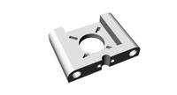
| 8 | LM8UU holder | RP | 
| |
| 3 | endstop-holder | RP | 
| |
| 1 | LM8UU x-end-idler | RP | 
| |
| 1 | LM8UU x-end-motor | RP | 
| |
| 1 | y motor bracket | RP | 
| |
| 2 | z motor-mount | RP | 
| |
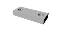
| 4 | belt clamp | RP | 
| |
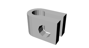
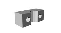
| 8 | bar clamp | RP | 
| |
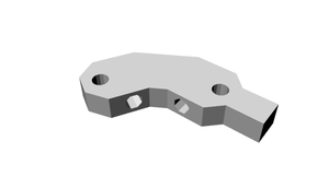
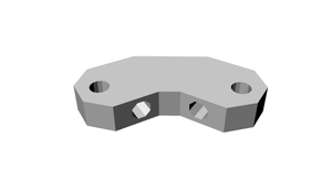
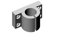
| 2 | rod clamp | RP | 
| |
| 2 | pulley | RP | 
| |
| 4 | frame-vertex with foot | RP | 
| |
| 2 | frame-vertex | RP | 
| |
| 1 | extruder block | RP | 
| |
| 1 | extruder idler block | RP | 
| |
| 1 | drive gear | RP | 
| |
| 1 | hub gear | RP | 
|
Smooth Rod
- 2x 410mm 8mm stainless steel round bar
- 2x 406mm 8mm stainless steel round bar
- 2x 350mm 8mm stainless steel round bar
Threaded Rod
- 6x 370mm M8 Threaded rod
- 4X 294mm M8 Threaded rod
- 3x 440mm M8 Threaded rod
- 2x 210mm M8 Threaded rod
- 1x 50mm M8 Threaded rod
Nuts, Bolts & Washers
- 100x M8 Nut
- 100x M8 Washer
- 5x M8 Mudguard washer
- 1x M8 Nyloc Nut
- 15x M4 nut
- 10x M4 Nyloc Nut
- 10x M4 Washer
- 4x M4 Wing Nut
- 3x M4 Bolt16
- 4x M4 Bolt50
- 6x M4 CSK Machine Screw 40mm
- 40x M3 Washer
- 80x M3 Nut
- 3x M3 Machine Screw 8mm
- 20x M3 Machine Screw 10mm
- 30x M3 Machine Screw 16mm
- 20x M3 Machine Screw 20mm
- 25x M3 CSK Machine Screw 12mm
- 2x M3 CSK Machine Screw 16mm
- 3x M3 Grub Screw 6mm
Belts
- 840mm x 5x T5 pitch timing belt
- 900mm x 5x T5 pitch timing belt
Bearings
- 6x 608zz
- 12x LM8UU Liner
Thick Sheet
- 1x 4mm aluminium heated print bed
100px Media:Longboat-Prusa-heated-print-bed.dxf
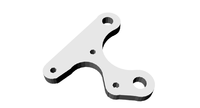
- 1x 4mm aluminium X-plate
200px Media:Longboat-Prusa-X-Plate.dxf
- 1x 4mm aluminium Y-plate
200px Media:Longboat-Prusa-Y-Plate.dxf
Heated bed parts
- 4x 1R HS25 resistors. HS25 1R J
Extruder parts
Hot End parts
Electronics
- Longboat all in one electronics board coming soonor any other version.
Steppers
- 5x NEMA 17 Bipolar stepper motors - SY42STH47-1684A
Assembly
Frame assembly
In this section we will be looking at the frame assembly.
NOTE: Even if you have assembled a RepRap Prusa before please read these instructions as our frame differers slightly from the standard Prusa.
Tools
30cm rule
M8 Spanner
Step 1 Frame triangles
Components
- 4x Frame Vertex with foot
- 2x Frame Vertex
- 2x Bar clamps
- 6x 370mm M8 Threaded rod
- 28x M8 Nuts Bag 1
- 28x M8 Washers Bag 2
Instructions
Divide the above components in to two even sets.
Take one of the lengths of threaded rod and slide a bar clamp to the middle. Place a washer and then a nut either side of the clamp.

Place a nut, washer and then a frame vertex with foot followed by a washer and the nut on to each end of the rod. Loosely tighten the nuts.


Attach two more lengths of threaded rod to each footed frame vertex, using a washer and nut either side as before.


Attach a non footed frame vertex to the connect up the triangle.
Repeat all the above instructions until you have two matching frame triangles.

Place each frame flat on you desk, using your ruler tighten the nuts until each side is 290mm (measure from plastic to plastic)

Step 2 Cross Bars
Components
- 4x Bar clamps
- 1x Y Motor bracket
- 2x 608zz Bearings
- 4x 294mm M8 Threaded rod
- 14x M8 Nuts Bag1
- 15x M8 Washers Bag2
- 4x M8 Mudguard Washers Bag 3
Instructions
Take the Y motor mount and attach a 294mm length of rod through the bottom hole, approximately half way along the rod. Fix in place with a M8 washer and M8 nut either side.

Take a Bar clamp and attach in to a 294mm length of rod, approximately a quarter of the way in from one end. Fix in place with a M8 washer and M8 nut either side. Then attach a M8 nut and M8 washer half way down the rod. Attach this rod through the top hole of the Y motor mount.

Add the following components, a M8 Mudguard washer, M8 washer, 608zz bearing, M8 washer, M8 Mudguard washer and then a nut.

Add a bar clamp to the rod attaching with a M8 washer and M8 nut either side.

On a new 294mm length of rod attach a 608zz bearing, followed by a M8 washer, M8 Mudguard washer and M8 nut either side. Attach the remaining two bar claps either side of this, attaching with M8 washers and M8 nuts either side.

Step 3 Frame assembly and jigging
Components
- 26x M8 Nuts
- 24x M8 Washers
- 3x 440mm Threaded Rod
Instructions
Take the rod assembly which has the two rods held apart by the Y motor mount, add a M8 nut followed by a M8 washer.

Take one of the frame triangles made earlier and attach the Y motor mount rod assembly through the holes in the frame vertex with foot. Attach in place with M8 washers and M8 nuts.

Attach the two remaining 294mm assembles to the other frame vertex with foot the same way as above. Note make sure the rods with the 608zz bearings are above the rods without bearings.

Prepare the opposite ends with M8 nut and M8 washer, attach the other frame triangle. Before attaching in place with a M8 washer and M8 nut measure the gap between the footed frame vertex's it needs to be 234mm from the inside to inside of the plastic frame vertex.


Stand the frame on the footed frame vertex's. Take a 440mm length of threaded rod slide half way through one of the holes on one of the non footed frame vertex, add a M8 washer, two M8 nuts and finally a washer. Slide this all the way through the opposite frame vertex hole. Turn the frame so that the side with the Y motor mount is facing you. Check that the spacing between the inside of the plastic frame vertex is 234mm as before. Maintaining this measurement adjust the rod so that there is 95mm of rod on the right side, measure from the out side of the plastic frame vertex. Add a M8 washer and M8 nut to secure this rod in place at each end. Repeat this process with the second 440mm length.

The four bar clamps now need to be spaced correctly, measuring from the inside of the nearest frame vertex, the nearest side of the the bar camp needs to be 40mm.

With the Y motor mount facing you the distance from the inside of the right frame vertex to the first mud guard washer needs to be 112mm.

The two bar clamps on the bottom of the frame triangles now need spacing correctly. The distance from the frame vertex to the bar clamp needs to be 129mm. NOTE measure from the frame vertex which is on the same side as the Y motor mount.

Now take the last 440mm length of threaded rod and screw it through the bar clamps. Turn the frame so that the side with the Y motor mount is facing you. There need to be 100mm of threaded rod on the right side, adjust the rod unit there is 100mm past the outside edge of the bar clamp. (Please note the photo shows 95mm and is incorrect)

Keeping the frame so that the Y motor mount facing you, add a further three M8 nut and one M8 washer to the upper right sides of the 440mm threaded lengths. Add one M8 washer to the upper left sides.


Step 4 Z axis mounts
Components
- 2x Z motor mounts
- 2x Rod clamps
- 2x Bar clamps
- 4x M3 20mm screw
- 4x M3 nut
- 4x M3 washer
Instructions
Insert a M3 nut in to each of the nut sized holes on the inside of the two Z motor mounts.

Attach a rod clamp to each of the Z motor mounts using two M3 20mm screws each with a washer.


Attach each a Z motor mount to either side of the upper 440mm threaded rods and attach in place with a M8 washer and M8 nut.


Keeping the frame so that the Y motor mount is facing you, add a M8 nut and M8 washer to the right side of the lower 440mm threaded bar, attach to this a bar clamp, and attach in place with a M8 washer and M8 nut. Repeat on the left side.

The inside edge of the bar clamp on the right side needs to be 72mm from the out side of the nearest bar clamp.

The inside edge of the bar clamp on the left side needs to be 61mm from the out side of the nearest bar clamp.

Y axis assembly
Components
- 4x LM8UU holder
- 2x Belt clamps
- 4x LM8UU liner bearing
- 20x M3 nut
- 20x M3 washer
- 20x M3 16mm screw
- 1x Y axis aluminium plate
Instructions
Attach each of the four LM8UU holder to the aluminium plate using the M3 16mm screws, the M3 washers go between the screw head and the aluminium plate.


Attach the two belt clamps but do not fully tighten, attach with two M3 16mm screws with M3 washers and M3 nuts, the plastic clamp needs to be on the opposite side to the LM8UU holders.


Take the two 410mm stainless steel round bars and slide them half way through the bar clamps which are either side of the Y motor mount.

Take the Y axis aluminium plate assembly and slide the two 410mm bars through the LM8UU bearings, continue to slide the rods until they pass through the opposite bar clamps. Space the spare round so that there is an even amount on either side.


Tighten the rod clamps and check the measurements are still correct, between 40mm and 41mm from the inside of the frame vertex to the inside of the rod clamp. Slide the Y assembly back and forth. If you feel any resistance slightly slacken the screws holding the LM8UU holders to the plate and then re-tighten, this ensures that the holders are seated properly.
X axis assembly
Coming soon.
Heated print bed
Coming soon.
Extruder and Hot End
Coming soon.
Wiring
Coming soon.
Commissioning
Coming soon.
Where To Purchase
http://www.thereprapkitstore.co.uk sell complete unassembled Longboat Prusa kits.