Microstepping with optical feedback
Release status: unknown

| Description | Microstepping with optical feedback
|
| License | unknown
|
| Author | |
| Contributors | |
| Based-on | |
| Categories | |
| CAD Models | |
| External Link |
Contents
Overview
Stepper motors with fewer than 400 steps per rotation are easy to find as surplus equipment, either by themselves, or in old computer printers. Optical encoder strips and quadrature optical encoders are easy to get from junk ink-jet printers. In order to allow retrofitting of existing systems, it is desirable to have a setup that can take the PULSE and DIRECTION command signals usually accepted by stepper motor driver boards. These items can be combined to make high precision motion control setup that is quite useful.
Interface to gcode interpreter
I intent was to make this setup act like a stepper motor driver board, which it does. Because the step signal (PULSE) is being sampled by firmware, I have a simple pulse stretcher circuit that makes the pulses a little longer. The gcode interpreter Arduino that I am using makes 5 microsecond pulses.
Stepper motor
This is a NEMA 17 motor on one axis, and larger cylindrical stepper on the other axis.
Drive Circuit
<schematic> The drive circuit uses a L2 This is connected directly to the stepper motor in a bipolar configuration. It is being driven with a 30KHz PWM signal. There is no output filtering on this signal, but I have not had EMI problems.
Feedback Loop
This system is a little different from a servo loop with a DC motor. If you put a voltage across the terminals of a DC motor, it revs up to a certain speed and will continue to rotate at that speed while the voltage is present. If you put voltages on the terminals of a stepper motor, it moves to a certain position, and then holds that position. This actually makes things easier.
Firmware
See attached file. This is an Arduino type .PDE file and can be compiled with the arduino development software. It does use a custom made interrupt routine, though.
Optical encoder
This is a quadrature optical encoder removed from a inkjet printer. It has built-in signal conditioning which means that it has digital outputs that can go directly to the arduino pins. They are also strong enough to drive a pair of diagnostic LEDs. These let you check the alignment of the optical strip. I use the optical strip from the same printer as the encoder, since the encoder is optimized for a certain stripe spacing.
Downloads
Photos and Drawings
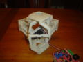
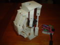
Model L04 closed
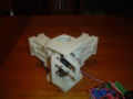
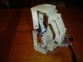
Model L04 halfway
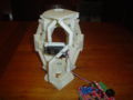
Model L04 open
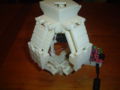
Model L04 back view
Model L04 side view
Model L04 side view


