Generation 2 Electronics
Contents
Generation 2 Electronics
Overview
Once you start putting electricity into your RepRap - even at just 12 volts - you have to take basic, common sense precautions to avoid fires. Just in case these fail, test your workshop smoke detector. Got no smoke detector? Get one!
Power Supply

The RepRap machine needs a regulated power supply giving at least 8 amps at 12 volts. The easiest way to do this is to convert a normal PC power supply into a RepRap power supply. Its simple, cheap, and all the boards are designed to accept the standard Molex connectors that are common on ATX power supplies.
More info and setup instructions here.
Individual Boards
Parts List
<iframe width='500' height='300' frameborder='0' src='http://spreadsheets.google.com/pub?key=pmEMxYRcQzzATwbOb71BmGA&output=html&gid=30&single=true&widget=true'></iframe>
Arduino & Arduino Clones

Arduino is an open source project that has created an easy and powerful microcontroller board. It is the brain of the RepRap electronics. You can get a premade Arduino, you can buy and assemble a kit, or you can even make it from scratch yourself. They all look the same to the rest of the electronics or to your computer.
More info and setup instructions here.
Stepper Motor Driver v1.1
<div class="thumb tright"></div>Each stepper driver board drives one of the stepper motors. You need three of these boards for a fully functioning RepRap. Each board controls the position of one axis. Together, they position the print head anywhere in the 3 dimensional build area.
More info and build instructions here.
DC Motor Driver v1.0
<div class="thumb tright"></div>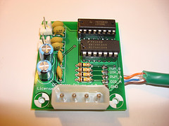
This board is capable of controlling two low current DC Motors in both forward and reverse. It has a speed/direction interface and is easy to control.
More info and build instructions here.
PWM Driver v1.0
<div class="thumb tright"></div>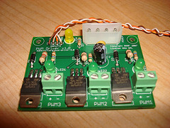
This board is capable of driving medium DC loads with TIP120 power transistors. It has a PWM interface and is also easy to control.
More info and build instructions here.
Opto Endstop v1.0
<div class="thumb tright"></div>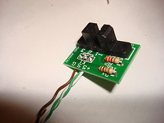
All of a RepRap's axes all need a datum (also known as home position or end-stop) to reference their movements. At the start of each build each axis needs to back up until the datum point is reached. We use one opto-switch for each axis to define its position. This page tells you how to wire one up.
More info and build instructions here.
Temperature Sensor v1.0
<div class="thumb tright"></div>
This sensor allows you to read a thermistor as an analog value. It is a very small and simple helper board.
More info and build instructions here.
Power/Communications Card v1.3
<div class="thumb tright"></div>
This is only needed in a Dual Arduino setup!!!
The Power / Communications card is the link between the computer and the RepRap printer. It uses RS232 to communicate over a serial port. If you do not have access to a serial port on your computer, there are widely available USB -> RS232 converters available. It also distributes the 12v power via connectors for all the other boards.
Signals are passed from the RS232 around the communications ring until they arrive at the device to which they are addressed, which then acts upon them. Thus the RS232 Transmit from the Communications board goes to the Receive on the first controller; that board's Transmit goes to the next board's Receive.
More info and build instructions here.
Set Everything Up
Now that all the boards are created, you'll need to wire it all up. One of the main advantages of the Arduino based system is that it is highly configurable. Each board can be wired to the Arduino in a number of ways. It is possible to run the electronics from one, two, or even more Arduinos. Our communications protocol is based on a token ring network, which makes it easy to add or remove parts from the system. You could even theoretically run Generation 1 PIC controllers and Generation 2 controllers in the same network, provided you hooked it up right.
First, you'll need to decide how you want to wire things up.
Single Arduino Setup
This is the easiest setup there is. We've done some creative wiring/coding and figured out how to run an entire RepRap machine off of a single Arduino! The token ring network consists of your computer and your Arduino, so it is very fast and easy to setup. You dont need any sort of serial connectors, and the Arduino can simply be powered directly off the USB port of your computer. The only real downside is that the code takes up most of the space on the Arduino, and every single pin is in use. Basically, there is not much room for hacking either the firmware or the electronics... but it will definitely get you printing in a minimum of time and effort.
The pin mapping table is below, along with a wiring diagram of how to connect the boards together.
Dual Arduino Setup
This setup is a bit harder, but it allows you much more freedom in the things you can do with both your firmware and your electronics setups. You will have quite a few pins free on both boards, as well as lots of flash memory on each Arduino available for hacking. This setup is ideal for developers and people interested in playing around with experimental electronics. You could theoretically add things like rotary/linear encoders, more limit switches, more temp sensors, more extruder heads, etc. This gives you the most freedom to tinker at the cost of a slightly more complicated setup.
The pin mapping tables are below, along with a wiring diagram of how to connect the boards together.
3 Axis Controller
This Arduino controls all the stepper motors, limit switches, etc. for your RepRap machine.
Extruder Controller
This Arduino controls a Thermoplast extruder for your RepRap machine.
Network Diagram
This is how you should wire the Arduinos, Power/Communications board, and your computer together.
Wire It Up
First, find or cut a flat piece of thin plywood, about 12" x 12".
Next, place all your boards on the wood so that each board is close to where it will be wired to. Mark with a pencil through each hole, and also optionally around each board for drill holes and as a board outline.
Then, take all the boards off and drill out each drill mark with a 1/8" (or 3mm) drill bit.
Take a foot or so of silicon aquarium tubing and cut short (1/4") lengths of it. You will be using these to mount the boards to the wood. Optionally, you can use spacers if you want a more professional look.
Now, mount each board on to the wood with M3 x 15mm bolts. Use washers on both sides, and use a short piece of tubing between the board and the wood for spacing (and shock absorbtion). Tighten down the nut by hand, and then a little bit with pliers or a wrench. It should be solidly attached, but not wrenched down too much. (For the brits: dont use too much welly ;)
Once you have the boards laid out and mounted, its time to wire them up. Currently, there are 3 different ways to hook the boards up to your Arduino:
- Strip 1/4" from the end of the wire, and stick it directly into the header on the Arduino. This is the easiest, but also most prone to failure (the wires will vibrate out, break, etc.)
- Solder the each wire to a .100 pin strip, and plug that directly into the appropriate spot on the Arduino. This is the hardest method, but it is the most permanent. The downside is that its hard to reconfigure your system without resoldering everything.
- We are working on an Arduino breakout shield which you will insert into the Arduino and provide the same access to the pins, but in a screw terminal form-factor. It will be a nice blend of easy configuration, with a strong, semi-permanent connection.
Program the Arduino
Once you have everything wired up and ready to go, its time to program the Arduino with the appropriate firmware. There are a few simple, easy steps to do this:
- Download and install the most recent Arduino program.
- Download the most recent RepRap Arduino firmware source.
- Copy the folders in the library folder of the file above into your Arduino library folder (arduino/hardware/libraries)
- Open the appropriate firmware in the file above and upload it to your Arduino board(s).
The appropriate firmwares are:
Single Arduino
/snap/Single_Arduino_SNAP/Single_Arduino_Snap.pde - just upload this file and you're good to go!
Dual Arduino
/snap/3Axis_SNAP/3Axis_SNAP.pde - this is the firmware to upload to the Arduino wired up as a 3 axis controller. /snap/Extruder_SNAP/Extruder_SNAP.pde - this is the firmware to upload to the Arduino wired up as an extruder controller.
Once you have compiled and uploaded your firmwares, you should be good to go! Fire up the RepRap host software, double check that you've specified the proper serial connection, and you should be good to go! We recommend using the various exerciser programs to test each part of your machine before you go ahead and print stuff. If all goes well, then you'll be printing in no time.
Cheers!