ExtruderImprovementsAndAlternatives
Contents
Extruder improvements and alternatives
Under construction.
Direct drive.
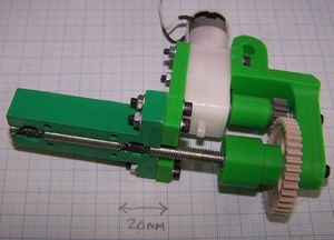
This is a replacement for the flexible drive. It is simpler, and less likely to wear out. Its only disadvantage is that it does not allow the working material a straight run down the extruder - it has to bend. For most working polymers introducing a shallow bend as they enter the extruder is not a problem.
You will need a different motor coupling to the standard one. The design for this is in the motor-coupling.aoi file, called motor-coupling-direct-drive. Export this as an STL and print it.
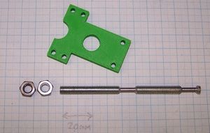
The M6 screw drive is also simpler to make, though it is longer. The reduced diameter bearing lands are in exactly the same arrangement as for the standard extruder, but there is no need to drill an end hole nor to make a separate short section to hold the drive nuts. The drive screw needs to be 96 mm long.
Solder two M6 nuts on the end, taking care to align their flats. Clean all grease and oxide from the screw threads and nuts, apply a thin film of solder flux, screw the nuts in place, then heat gently with a blow torch. Use ordinary electronic solder.
High-temperature heater design
This idea comes from reprapper Ian Adkins of Bits from Bytes.
JB Weld is fine up to about 190 oC. But if you want to go hotter, you need something tougher.
Fire cement fills the bill. It is available from hardware shops and plumbers' suppliers. It is used to fill cracks in chimneys and to seal round flues. The stuff I got goes up to 1250 oC, but don't regard that as a target - you'll degrade the PTFE to some nasty poison gases. the high two-hundreds are a sensible limit.
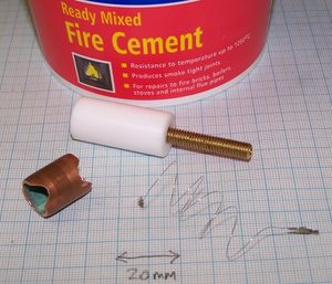
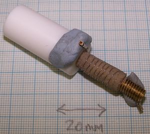
The picture on the right shows the parts you will need: fire cement, the standard PTFE cylinder, the standard brass M6 threaded tube, an 8 ohm length of nichrome heater wire, and an 18 mm length of 15mm diameter copper tube.
You will also need a K-type thermocouple. The extruder heater will get too hot to use thermistors. Thermocouples will be fine, though; unlike thermistors, they also give a linear output with temperature, which makes things simpler.
File two notches in the copper tube at the ends as shown. These will be used to lead the electrical connections through.
The nichrome heater wire doesn't need to be covered in fiberglass insulation, which will make it cheaper and easier to get (maybe from old electric heater?). You definitely can't solder connections to it as it will get too hot and melt the solder. Crimp on two small connectors as in the picture; alternatively use screw connectors.
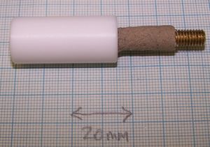
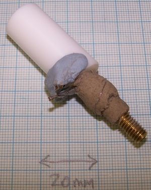
Start by applying a layer of fire cement to the brass tube about 1mm thick and 18 mm long. You will probably find this easier to do with your fingers than with tools. It is also easier to apply too much, then to trim it away with a blade, and then to roll the result between your fingers to smooth it.
Partly set the fire cement with a hair dryer. You don't need to set it completely. Just get it to the point where it is firm and has a dry skin on it.
Use Blu-Tack to hold one end of the wire against the PTFE as shown. Wind the rest of the wire evenly over the fire cement, and secure the other end with Blu-Tack.
Check that the wire's resistance is still 8 ohms (that is, check that it is not shorted against itself). Also check that the resistance between it and the brass tube is infinite - again, no shorts.
Apply a second coat of fire cement. Don't completely cover the wire - you will need to unwind it and lead it back to the top as shown. Again dry the cement with a hair dryer.
Check the resistances again.
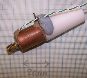
Push the copper tube over and get it roughly central. It may be simpler to have it slightly off-centre to accommodate the connections. This doesn't matter.
Push the thermocouple into the cement at the bottom.
Completely fill all gaps with fire cement. Push it in and tamp it down with a small screwdriver, but take care not to disturb the wire coil.
Again check the resistances, this time also making sure that the copper tube is isolated too, and that so is the thermocouple.
Clean the thread by running an M6 nut down the brass.
Attach the thermocouple to the RepRap thermocouple circuit and attach that to an Arduino as described on that page. Load the thermocouple program at the foot of that page into the Arduino and run it. The temperature should read room-temperature.
Attach a variable-voltage power supply to the heater coil and place the extruder heater vertically. It's going to get hot, so if (unlike me) you value your bench you may care to stand it on a small block of wood.
Turn on the power supply. Start with about 3v and check that the temperature rises slowly.
Over the space of a few hours come back and increase the voltage by about 0.5 v every so often. The idea is to ramp the temperature up very slowly to dry everything out without subjecting it to thermal stress. Stop when you get to about 250 oC.
Closed loop.
Locked clutch
Spacers at the top, very strong springs at the bottom
e.g.1.5mm x 9mm x 25mm.
Sharpened thread
Pipe clip on the PTFE
-- Main.AdrianBowyer - 12 Jul 2008
