Stepper Motor Driver 1.2
Contents
Stepper Motor Driver v1.2
Overview
<div class="thumb tright"></div>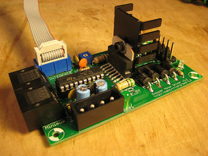
This board allows you to control one stepper motor, as well as receive input from two limit switches. It is based around the L297/L298 stepper driver combo. The L297 takes the signals from your microprocessor and translates them into stepping signals to send to the L298 which actually drives your stepper motor. The L298 is capable of driving up to 2A per coil. One interesting feature of the L297 is its current sensing and 'chopping' abilities. The L297 will sense the amount of current flowing through the coils, and will 'chop' the signal to the L298 so that the average current flowing is the desired amount. You can configure this current by setting the trimpot on the board and measuring the voltage on the test point.
At the bottom of the page is a section showing how to run this board off a single 12v supply. This will allow you, for example, to run your RepRap machine off a car battery if you want.
- You'll need a soldering toolkit to do most of this.
- Read our Electronics Fabrication Guide if you're new.
Get It!
Full Kit
Raw Components
Files
<div class="thumb tright"></div>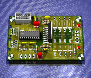
You can download the release file from SourceForge that has a bunch of helpful files for this board. It contains:
- GERBER files for getting it manufactured
- PDF files of the schematic, copper layers, and silkscreen
- Eagle source files for modification
- 3D rendered image as well as POVRay scene file
- exerciser code to test your board.
Schematic
<div class="thumb tright"></div>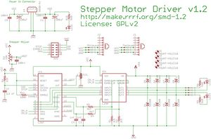
Configuration
Stepping mode
<div class="thumb tright"></div>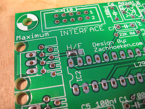
You need to select a stepping mode for your board to run!
This is a solder jumper. You connect the center pad to either the left or the right pad to select the state of the jumper. Use enough solder to bridge the two pads. Generally you will only want to select the stepping mode once, at the very beginning of board construction. Half stepping means the stepper takes twice as many steps, whereas full stepping means the stepper takes its normal number of steps. Half stepping is highly recommended.
- H* means half-stepping
- F* means full-stepping
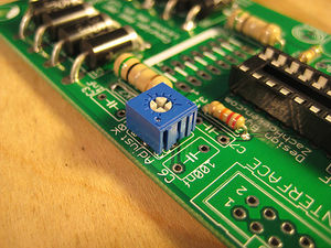
Current Adjustment
The board allows you to control the amount of current flowing through the coils by adjusting a trimpot located on the board below the 'Max' header. Simply turn the trimpot one direction to get the minimum current, and the other direction to get maximum current. Generally this will be clockwise/counter clockwise, but it will be obvious which is which as you adjust the current with the motor running. Adjusting it to the lowest setting will cause the motor to stop turning. Generally, you will want to adjust this to the lowest setting you need that will still turn the motor. That will reduce power usage, and will prevent your motor from overheating.
Interface
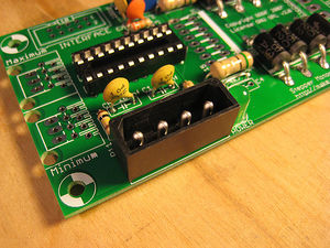
IDC Connector
| Pin | Name | Function |
| 1 | VCC | 5V input. Not connected on this board. |
| 2 | GND | Connect this to Arduino to share a common ground. |
| 3 | Step | A pulse on this line will make the stepper motor advance one step in the desired direction. |
| 4 | Dir | If this pin is high, the motor will rotate forward, low it will rotate backwards. |
| 5 | Enable | This pin allows you to turn the motor on and off. By default it is pulled high. A high signal means on, low signal means off |
| 6 | Min | This is the signal from the 'min' sensor. The definitions of high/low are determined by your opto endstop. |
| 7 | Max | This is the signal from the 'max' sensor. The definitions of high/low are determined by your opto endstop. |
| 8 | N/A | Reserved. This pin is not currently used. |
| 9 | N/A | Reserved. This pin is not currently used. |
| 10 | N/A | Reserved. This pin is not currently used. |
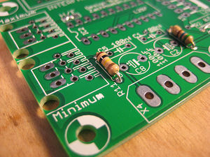
Minimum and Maximum Connectors
Say it with me:
The Stepper Motor v1.2 design does not support ethernet!
The Stepper Motor v1.2 design does not support ethernet!
The Stepper Motor v1.2 design does not support ethernet!
What we are doing is hijacking a common and very cheap connector for our own purposes. RJ45 patch cables and jacks are ubiquitous, versatile, robust, and cheap. We've considered and rejected many other connector technologies (RJ11, 3.5mm audio cables, etc) but in the end, RJ45 is the best for our needs. If you have another source of high quality premade cables (that we have not already rejected) please bring it to our attention in the forums. Please do not complain about being forced to use these cables, as there is a simple on-board alternative (see below).
Below you will find a pin out table containing the pin-out information on a standard RJ45 patch cable.
| Pin | Color | Function |
| 4 and 5 | Blue and Blue/White | 5V supply |
| 6 | Green | Signal |
| 7 and 8 | Brown and Brown/White | Ground |
.100" Spaced Header
<div class="thumb tright"></div>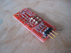
In order to maintain backwards compatibility, as well as giving the user the freedom to chose their desired connector technology, we have included a standard, .100" pitch connector footprint that you may populate as desired. The pins are clearly labeled, and you may wire it however you like. You can solder wires directly to the board, solder in right-angle headers, normal headers, or any other number of technologies. Its up to you as a user to decide. Shown here is an example of using a right-angle .100" spaced header.
Output
<div class="thumb tright"></div>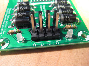
The L298 is rated for 2A per coil, so if your stepper motor drives more than that, you should adjust the chopper so that it delivers less current than that.
| Pin | Function |
| A | This is the 'positive' end of coil 1 |
| B | This is the 'negative' end of coil 1 |
| C | This is the 'positive' end of coil 2 |
| D | This is the 'negative' end of coil 2 |
We have a page with full info on wiring your stepper motor for use with this board.
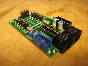
Circuit Board
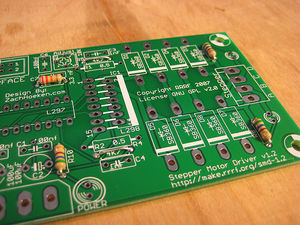
<div class="thumb tright"></div>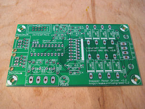
You can either buy this PCB from the RepRap Research Foundation, or you can make your own. The image above shows the professionally manufactured PCB ready for soldering. Its also cheap, only $5.00 USD. It is also apparently possible to build it on stripboard - if you do so, please share the instructions with us!
Components
<div class="thumb tright"></div>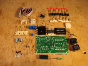
<iframe src="http://parts.reprap.org/embed/module/Stepper+Motor+Driver+v1.2" width="600" height="800" frameborder="0">Visit http://parts.reprap.org/embed/module/Stepper+Motor+Driver+v1.2</iframe>
Build Process
<div class="thumb tright"></div>Solder Jumper
The first thing you should do is set the solder jumper to the proper configuration. The meaning of this jumper is discussed above. To set it, simply 'bridge' the appropriate pads together with some solder. This forms a semi-permanent connection. If you decide to change your mind, you can simply de-solder the jumper and re-solder it how you want. 99% of the time you'll simply want to set it and forget it.
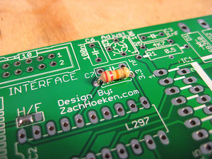
R6 - 22K - Red/Red/Orange
This is a 22K ohm resistor. Solder this resistor in the appropriate places. Make sure you double check the color codes to make sure you're putting the proper resistor in the proper place. You can insert the resistor in any orientation into the board.
R4, R5
These are optional resistors. Don't use them unless you know that you need them. If you don't know if you need them or not, you don't need them. =) Instead, solder some pieces of wire in their place.
R8-R10 - 560 ohm - Green/Blue/Brown
These are 560 ohm resistors, used to limit the current flowing through the LEDs. Solder these resistors in the appropriate places. Make sure you double check the colour codes to make sure you're putting the proper resistor in the proper place. You can insert the resistors in any orientation into the board.
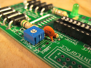
R11 - 100 Kohm - Brown/Black/Yellow
This is the 100K ohm pullup resistor to enable the driver by default. Make sure you double check the color codes to make sure you're putting the proper resistor in the proper place. You can insert the resistor in any orientation into the board. Inserting from the printed side is the recommended method.
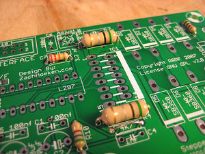
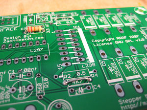
R1, R2 - 0.5 ohm - Green/Black/Silver
These are the bigger, 0.5 ohm resistors with thicker leads. More challenging to thread through. Solder these resistors in the appropriate places either side of IC1. You can insert these resistors in any orientation into the board.
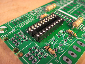
Socket
Now is a good time to solder the DIP socket into the board. Try to get it as flush with the board as possible, and note that there is a notch in the "pin 1" end. I like to solder a corner pin, then solder the opposite corner pin to lock the socket into place as I solder the rest.
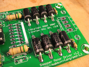
D1-D8
First insert all the diodes into place. Bend the leads with your hands or with some pliers, as close to the body as you can. Then, insert the component so that the band one one end matches up with the band on the silkscreen. Make sure you get these right!!! After you have inserted all the components, flip the board and solder them all in.
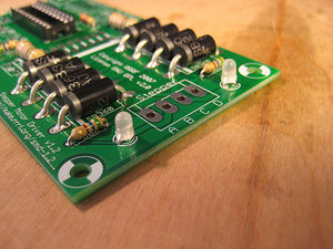
LED2, LED3
These are the bicolor LEDs. Orientation does not matter a whole bunch, but its a good idea to put the short leg into the hole nearest the flat part on the silkscreen.
R3 - 10K
This is the trimpot. There are numbers on it, that match up with the numbers on the silkscreen. Insert it accordingly, and solder it in. If it is inserted incorrectly, it will not ruin your board, but the current increase rotation direction will be reversed.
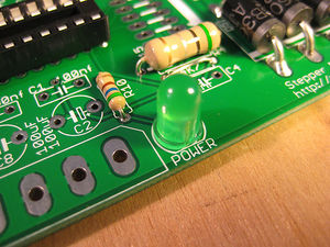
LED1
This is the power on LED. Orientation is important, so make sure you put the short leg into the hole nearest the flat part on the silkscreen. The LED itself should also have a flat side, which should match up to the silkscreen.
C7
This is the 3.3nF ceramic capacitor. It will have something like '332' written on the side. Solder it into place next to the diodes. Orientation does not matter.
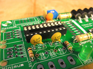
C1, C5, C6
These are the 100nF ceramic capacitors. They will have something like '104' written on the side. Solder them into place, orientation does not matter.
POWER
This is the power connector for the board. It is a standard socket that accepts a power cord from a standard PC power supply. Match up the notches on the inside of the connector with the markings on the silkscreen. Solder it in, and make sure you use plenty of solder.
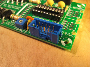
IDC Header
This is the header for your interface connector. The polarity is important here, so make sure you insert it correctly. There is a gap on the front that matches a notch on the silkscreen. There is also an arrow on the front that should correspond to pin 1.
As with the IC socket solder opposite corners in place while keeping the socket located snugly, and then do the remaining pins.
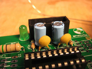
C2, C8
These are the electrolytic capacitors. They have only one orientation you can solder them in. One side is marked negative (with '-' going down one side.) The other lead is longer and should be inserted into the hole marked '+'. Both negatives should face each other in this instance.
Stepper
This is the stepper header. Solder it with the tabs facing the inside of the board. Make sure it is nice and flush with the board. If you ordered it from Mouser, it comes as part of a breakaway header. Use wire clippers to cut the plastic joiners apart to make it the correct width.
RJ45 Jacks
THIS BOARD DOES NOT SUPPORT ETHERNET! We are simply using the jack to provide simple, easy, cheap connectors.
These are the jacks for the minimum/maximum opto endstops. They can only be inserted in one orientation and should snap into place for easy soldering.
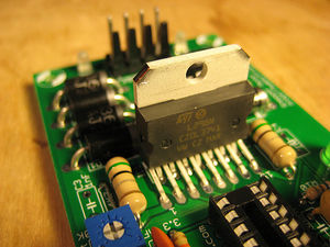
IC1
This is the L298 chip. You will only be able to insert it into the board in one orientation. Once you have inserted it, solder it in. Take care not to use too much solder so that it doesnt bleed through and bridge where the leads come together.
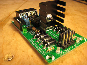
Attach Heatsink
It is easiest if you mount the heatsink with the tabs extending out over the diodes with the large side on the top. Take care that you do not accidentally short anything.
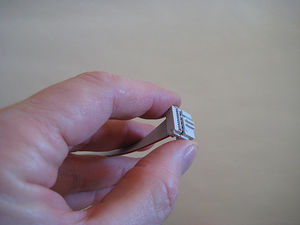
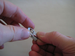
Crimp IDC
Locate the triangle on the IDC plug. It marks pin one, which corresponds to the red stripe on the cable. Lay the cable so its end is flush with the edge of the plug, and the plug is at right angles to the path of the cable.
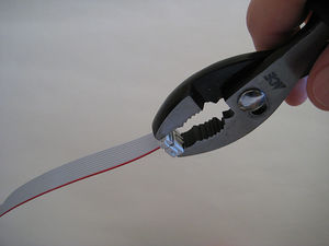
Using gas (slipjaw) pliers or some other crushing implement with parallel jaws such as a bench vice, crimp the top of the plug onto the bottom of the plug.
Attach Strain Relief
The IDC strain relief is a C shaped piece of plastic the same color as the IDC plug. Bend the cable backwards over the top of the plug and attach the strain relief. This helps to prevent the cable from loosening when you pull the plug out of its socket.
Do the same for the other end of the cable, matching the red stripe to pin one marked by the red triangle. Depending on which way you lay the cable, remember that it will exit the other way once you attach the strain relief. Electrically it doesn't matter, but physically you might want the cable to exit one way or the other.
Optional Components
If you don't know what these are for, you don't need them. They are there for experimenters who are deviating from the standard build.
R4, R5
These are 4.7K ohm resistors. Earlier we told you to solder a wire in the place of these resistors. Instead, solder these resistors in the appropriate places. Make sure you double check the color codes to make sure you're putting the proper resistor in the proper place. You can insert the resistor in any orientation into the board.
C3, C4
These are the 1nF ceramic capacitors. They will have something like '102' written on the side. Locate the rectangles labelled C3 and C4. They will say "1nF" next to them. Solder them into place, orientation does not matter.
Test Your Board
Now we have to test the board. Its very easy, and consists of a few steps.
Connect Power to Board
Always turn your power supply off before plugging it in. It won't fry things most of the time... but all it takes is once to damage things.
Simply take your AT power supply and plug a power connector into the board, and turn it on. The green LED next to the connector should light up. If it doesn't, check its polarity and bust out your multimeter!
Turn your power supply off while you plug boards together!
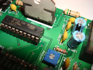
Insert L297 chip
Turn the power off!!
Now that the power is off, it is time to insert the chip that tells the L298 when to turn on and off. Line up the semicircle on the chip with the semicircle on the silkscreen (and the chip socket if you did it right :) ) Make sure all the legs are properly in the socket, and fully insert it. You shouldn't need to remove it after this, so feel free to push it all the way in. Note that this photo is of a v1.0 board, but the chip still goes in the same direction in the socket.
Now that your chip is fully inserted, turn the power back on. The LEDs next to the stepper header should also light up, as the stepper is enabled by default. If they both do, then chances are your circuit is working properly!
Give it a test drive.
Connect Board to Arduino.
This part is very easy. Use the table below to determine what pins to hook up to what. Plug the IDC cable into the blue socket on the stepper controller board. If you look into the holes of the IDC plug, with the red stripe away from you, the top-right pin is #1. The pin to its left is #2. The pin one row closer to you from #1 is #3. The pin closer to you from #2 is #4. Plug three jumper wires from the IDC connector into the associated Arduino pin:
| Board Pin | IDC | Arduino Pin |
| STEP | 3 | 4 |
| DIR | 4 | 5 |
| GND | 2 | Ground |
Upload Firmware to Arduino
Now, feel free to turn on the power to your power supply. Next, open the Arduino software, copy the code below into your sketch and upload it. After the firmware has compiled and uploaded, the Arduino will restart and the exerciser will begin shortly.
#define stepPin 4 #define dirPin 5 void setup() { Serial.begin(9600); Serial.println("Starting stepper exerciser."); pinMode(stepPin, OUTPUT); pinMode(dirPin, OUTPUT); digitalWrite(dirPin, HIGH); digitalWrite(stepPin, LOW); } void loop() { int i, j; for (i=1650; i>=600; i-=150) { Serial.print("Speed: "); Serial.println(i); for (j=0; j<2000; j++) { digitalWrite(stepPin, HIGH); delayMicroseconds(2); digitalWrite(stepPin, LOW); delayMicroseconds(i); } delay(500); Serial.println("Switching directions."); digitalWrite(dirPin, !digitalRead(dirPin)); for (j=0; j<2000; j++) { digitalWrite(stepPin, HIGH); delayMicroseconds(2); digitalWrite(stepPin, LOW); delayMicroseconds(i); } delay(1000); Serial.println("Switching directions."); digitalWrite(dirPin, !digitalRead(dirPin)); } }
The basic way the motor exerciser works is this:
- The stepper will take 2000 steps in one direction
- The stepper will take 2000 steps in the opposite direction
- The speed will increase or decrease.
The stepper exerciser will gradually increase/decrease the stepper motor to show a wide range of possible speeds and movements. It will do 2000 steps in each direction at each speed.
You can easily visually verify that the stepper motor driver is working after you do this, as the LED's next to the stepper driver will light up with an orangeish color. This is because the LED's are switching from green to red very rapidly. If this is happening, then congratulations: your stepper driver board is a success!
<object type="application/x-shockwave-flash" width="400" height="300" data="http://www.vimeo.com/moogaloop.swf?clip_id=419702&server=www.vimeo.com&fullscreen=1&show_title=1&show_byline=1&show_portrait=0&color=01AAEA"> <param name="quality" value="best" /> <param name="allowfullscreen" value="true" /> <param name="scale" value="showAll" /> <param name="movie" value="http://www.vimeo.com/moogaloop.swf?clip_id=419702&server=www.vimeo.com&fullscreen=1&show_title=1&show_byline=1&show_portrait=0&color=01AAEA" /></object>
Hook up a stepper motor
You'll need a stepper motor to drive at this point.
Find a stepper motor that you have wired up to a .156" pitch connector. You can view wiring diagrams for various stepper motors if you have not wired any up yet.
Make sure the power to your driver board is off and insert the connector. Reset the Arduino board and turn the power on for your power supply. After a few seconds, your stepper motor should spring to life. When it does, do a little dance because you've just cleared the hardest hurdle in making a robot that can do some amazing things.
Troubleshooting
- First, check to see that you have supplied power to the board.
- If that doesn't work, check that you have the board wired up correctly to the Arduino.
- If the motor does not move at all, then check your circuit for shorts and dry joints.
- If the motor does not move, but is very jerky, then you have miswired the stepper to the board. Simply reverse the polarity on one coil to make it function properly. (eg. switch A with B)
Hacks!
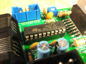
Run off a single 12v supply
It is easy to adapt the stepper board so that it will run from a single 12v supply. The picture on the right shows a screw connector bringing in 12v (black stripe) and ground (white) wires. Under the screw connector, and inserted in the holes on the board before the connector was soldered in, is a 78L05 5v regulator. Its ground pin goes to one of the two central grounds. Under the board (and so invisible here) that pin is bent over and soldered to short the two central ground connectors together. The input to the 78L05 goes to the 12v input under the screw connector. The 5v output from the chip goes to the 5v input hole on the board.
That is all that is needed to run this board of a single 12v supply. Take care not to short the 12v line to ground by running the input to the 78L05 too near the ground connector.
The next generation of this board will have space for the 78L05. You will be able to choose to put that chip in, or replace it with a jumper and thus run the board off a (5v, 0v, 12v) supply as is the standard now.
Making a 0.5 Ohm 2 Watt Resistor
2 Watt 0.5 Ohm Resistors can be hard to get in some locations. Many stores don't stock 2W resistors, going from 1W to 5W - and the 5W are large beasts with thick wires. 0.5 Ohms is an unusual value for a resistor too. Fortunately, using two 1 Ohm 1 Watt resistors wired in parallel works just fine.
History
Changelog
- fatten ground wires!!!
- fatten all wires too
- make board bigger to accomdate
- extra mounting holes
- test/add pullup resistor on enable
- test/add pullup resistor on reset
- wire cntl directly to vcc
- combine two grounds
- wire reset directly to vcc
- fix silkscreen on min/max
- power-on LED indicator
- bicolor LED's on output (one per channel, color indicates polarity)
- remove unneeded jumpers
- add test point for trimpot
- remove unneeded input pins
Previous Versions
- An incremental improvement of the Stepper Motor Driver v1.0
- Which is a board to replace the Universal Controller v1.2