File list
This special page shows all uploaded files.
| Date | Name | Thumbnail | Size | Description | Versions |
|---|---|---|---|---|---|
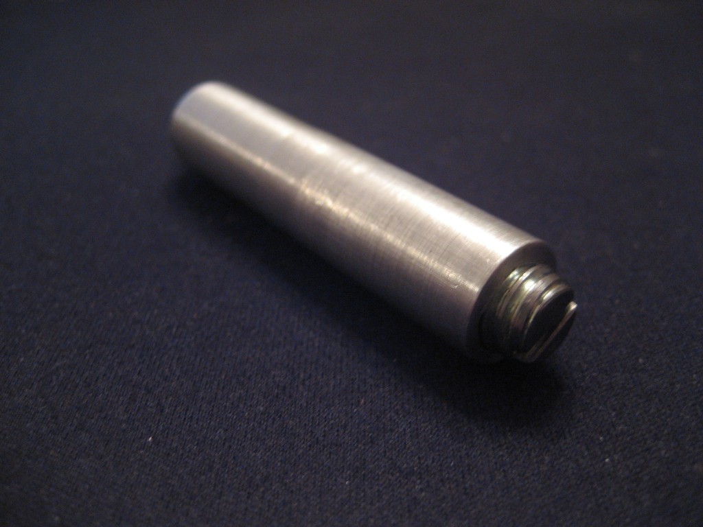
| 01:45, 11 April 2010 | Waxuum5.jpg (file) |  |
81 KB | Push-to-connect fitting visible on back. | 1 |
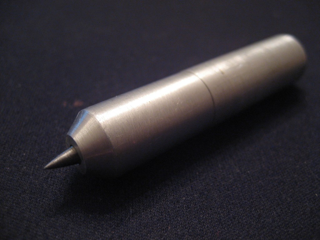
| 01:46, 11 April 2010 | Waxuum9.jpg (file) |  |
82 KB | Closeup view of nested drain and vent tubes at the cutting tip. | 1 |
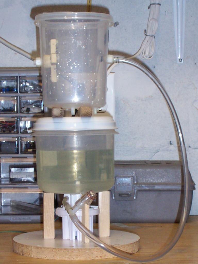
| 01:47, 11 April 2010 | Waxuum8.jpg (file) |  |
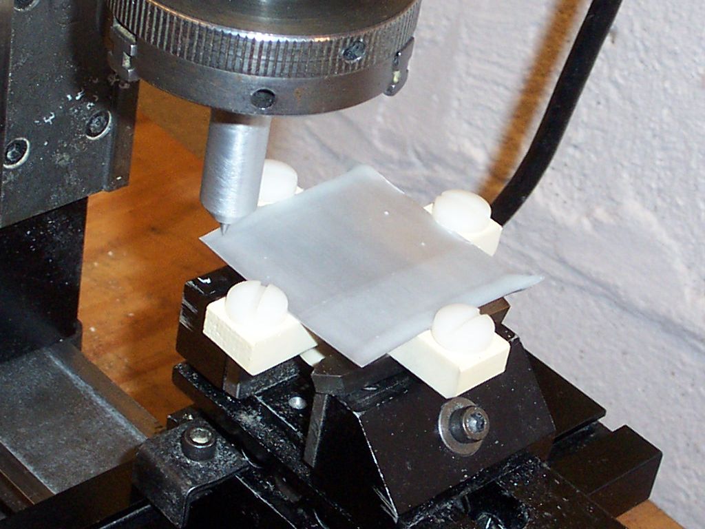
178 KB | A view of the test setup. Of course, this tool is meant to be installed on an automatic XYZ table (like RepRap or MakerBot) but for a quick test it was installed on the little manual Sherline. The waxuum was simply clamped to the vertical stage of the m | 1 |
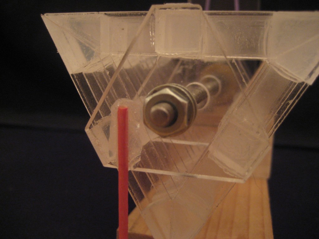
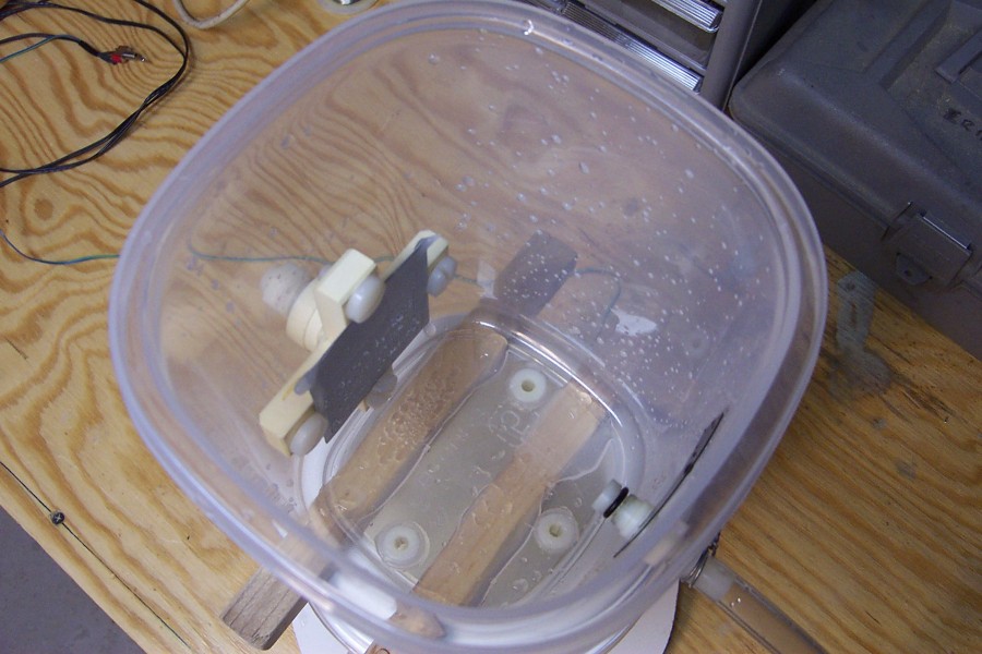
| 01:49, 11 April 2010 | Waxuum11.jpg (file) |  |
138 KB | Closeup of case at beginning of test. The wax inside is molten so the interior is visible. Near the top of the case interior, note the slanted cut in the drain tube, where the thinner vent tube passes out and outside. Molten wax exits from the slanted | 1 |
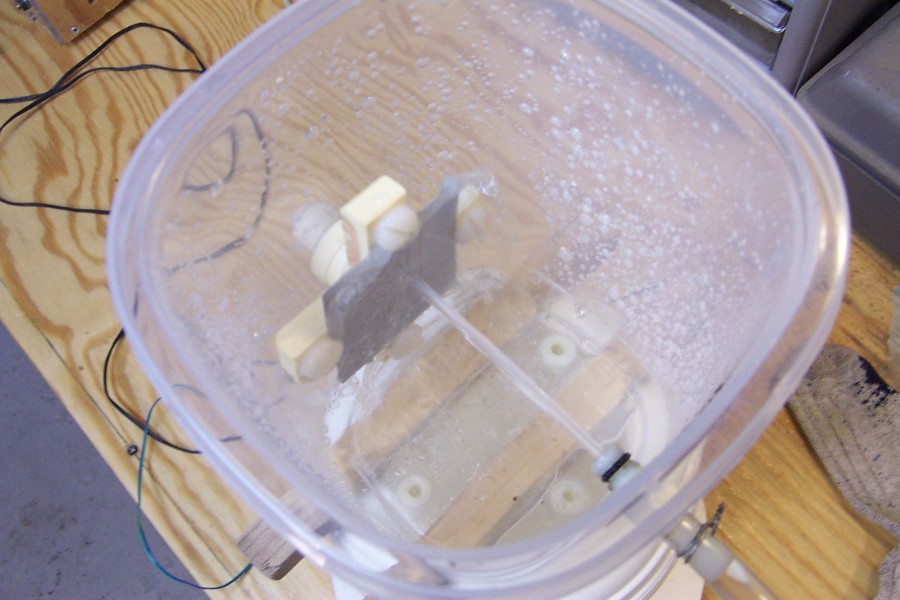
| 01:49, 11 April 2010 | Waxuum12.jpg (file) |  |
158 KB | Later in the machining process. Note more wax has been collected. | 1 |
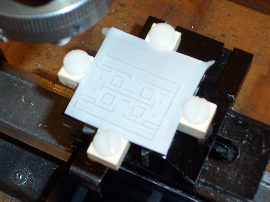
| 01:50, 11 April 2010 | Waxuum13.jpg (file) |  |
162 KB | The finished wax master. The part is just a little do-nothing brick - it is not really a functional item. | 1 |
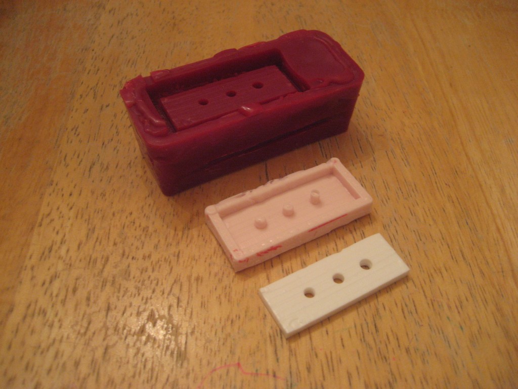
| 01:51, 11 April 2010 | Waxuum10.jpg (file) |  |
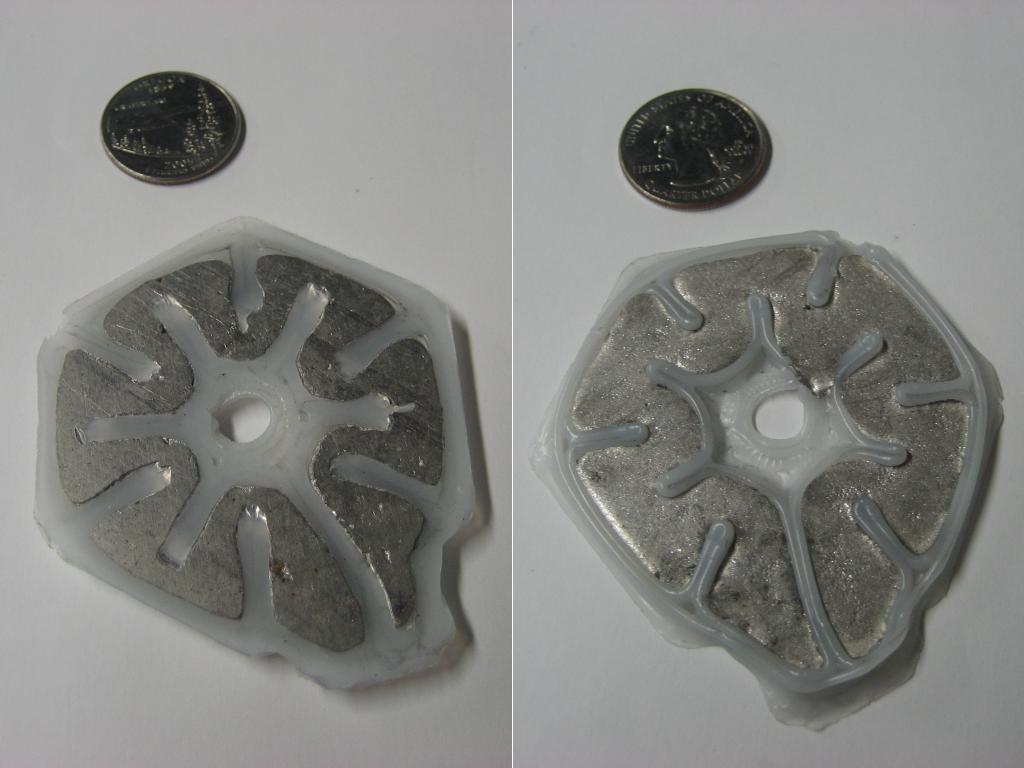
146 KB | Wax master, silicone mold, polyurethane part. | 1 |
| 00:40, 25 May 2010 | ComLinMech1.jpg (file) |  |
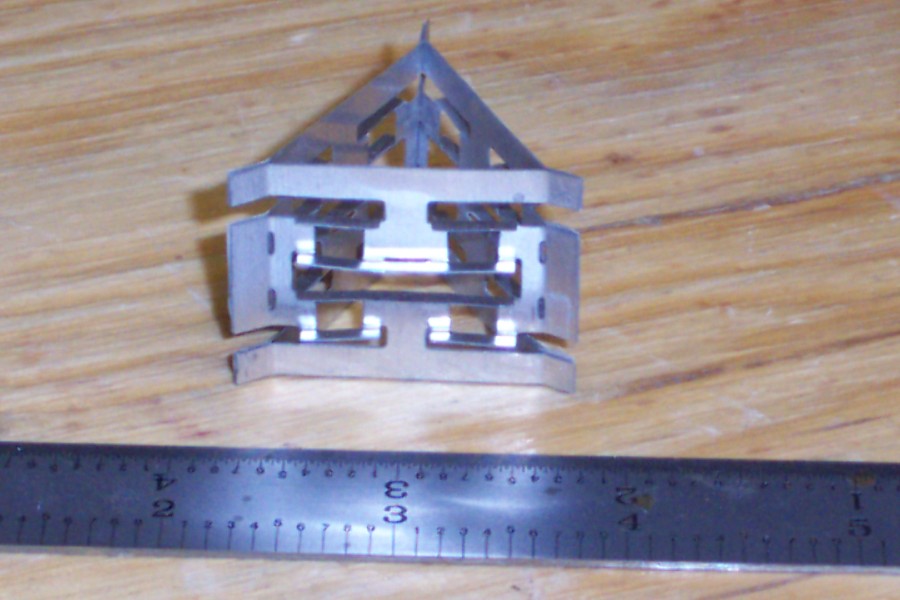
147 KB | Three prototype compliant linear motion mechanisms | 1 |
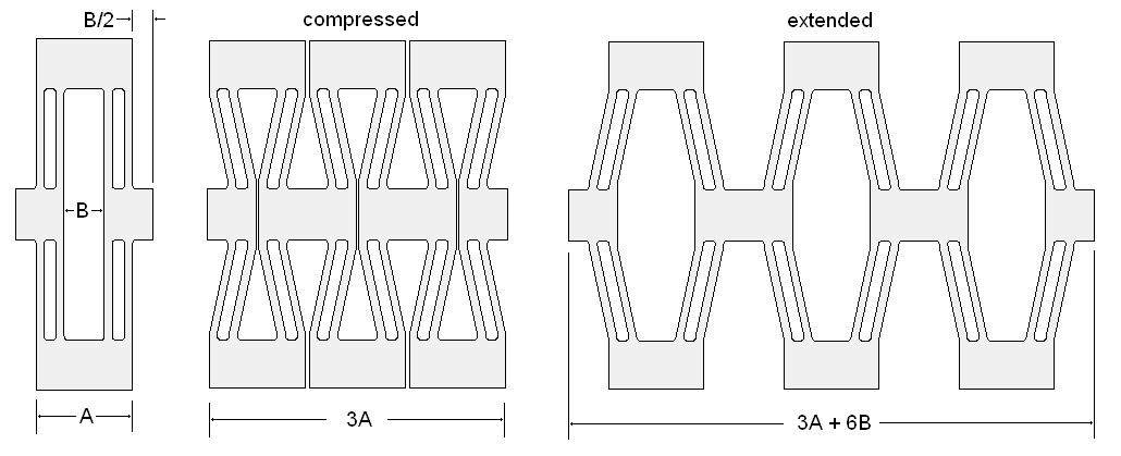
| 01:05, 25 May 2010 | Link-cartoon2.PNG (file) |  |
25 KB | Compressed, equilibrium, and extended cases of planar compliant mechanism. | 1 |
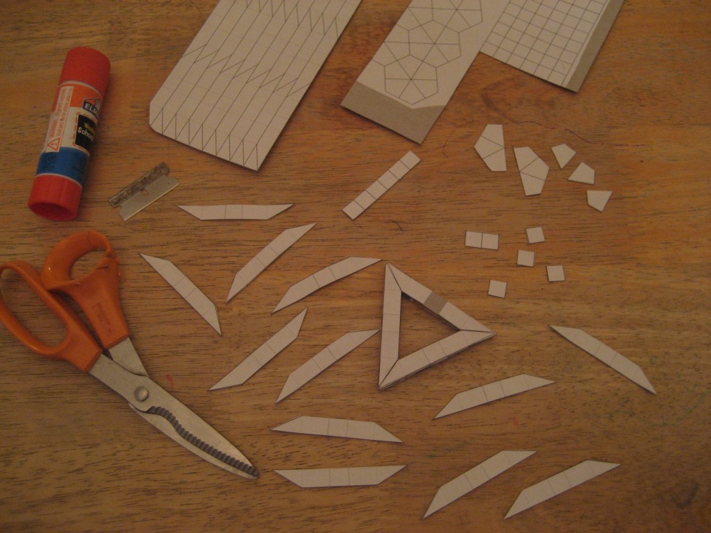
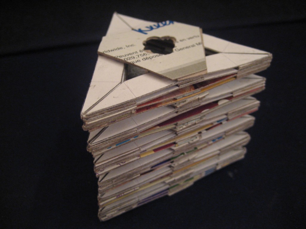
| 01:06, 25 May 2010 | ComLinMech2.jpg (file) |  |
167 KB | Building the cardboard version. | 1 |
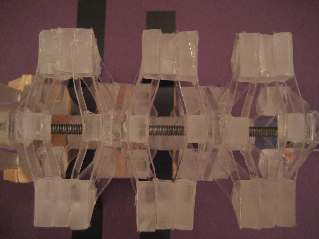
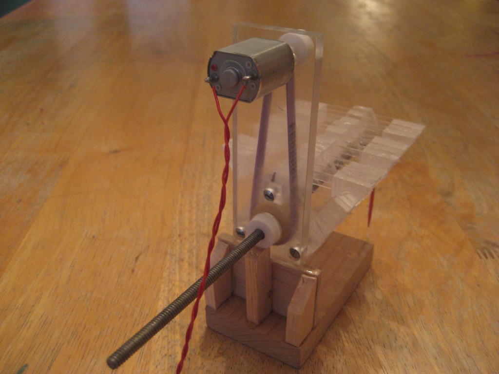
| 01:08, 25 May 2010 | ComLinMech3.jpg (file) |  |
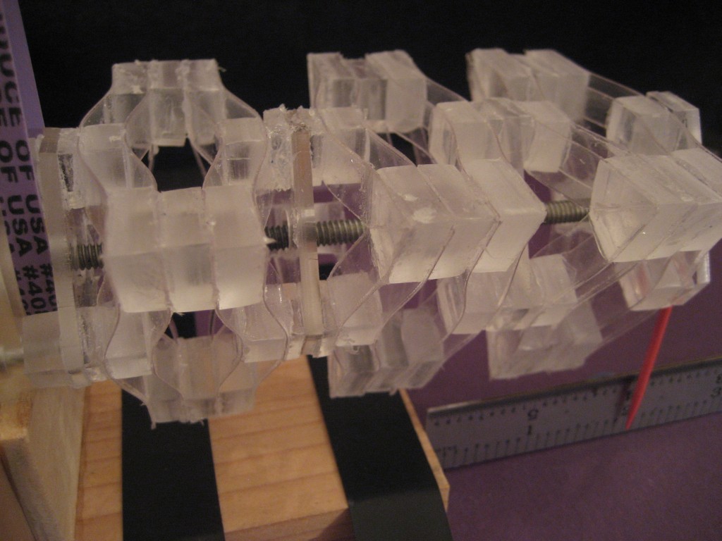
139 KB | Plastic compliant linear motion mechanism, extended. | 1 |
| 01:08, 25 May 2010 | ComLinMech4.jpg (file) |  |
138 KB | Plastic compliant linear motion mechanism. | 1 |
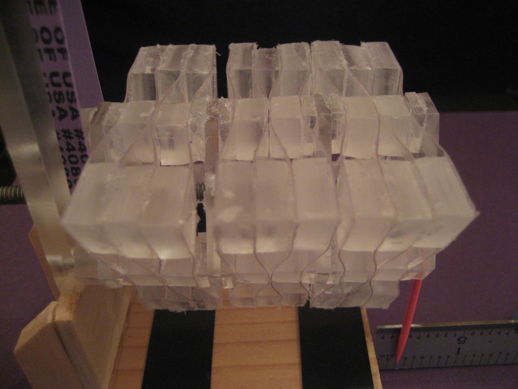
| 01:09, 25 May 2010 | ComLinMech5.jpg (file) |  |
128 KB | Plastic compliant linear motion mechanism. | 1 |
| 01:09, 25 May 2010 | ComLinMech6.jpg (file) |  |
130 KB | Plastic compliant motion mechanism. | 1 |
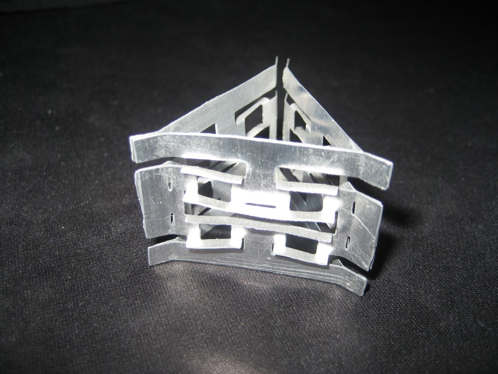
| 01:10, 25 May 2010 | ComLinMech7.jpg (file) |  |
183 KB | Aluminum compliant motion mechanism. | 1 |
| 01:12, 25 May 2010 | ComLinMech8.jpg (file) |  |
130 KB | Cardboard prototype compliant linear motion mechanism. | 1 |
| 01:13, 25 May 2010 | ComLinMech9.jpg (file) |  |
134 KB | Motor view - compliant mechanism. | 1 |
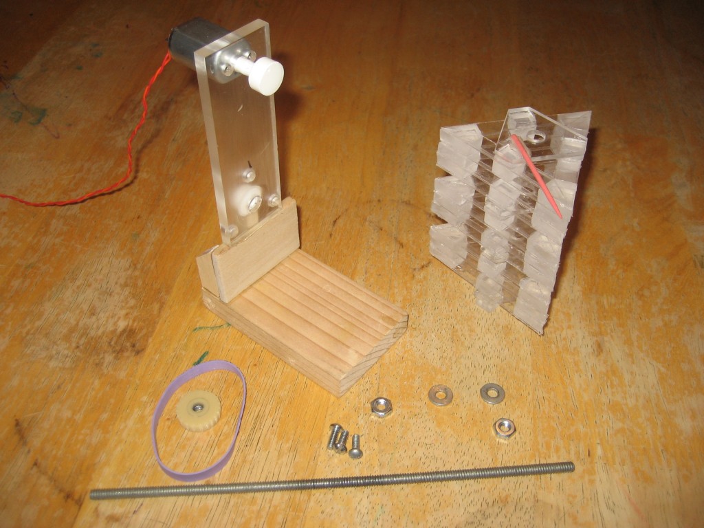
| 01:13, 25 May 2010 | ComLinMech10.jpg (file) |  |
177 KB | Compliant motion mechanism - disassembled. | 1 |
| 01:14, 25 May 2010 | ComLinMech11.jpg (file) |  |
148 KB | Self-supporting without leadscrew. | 1 |
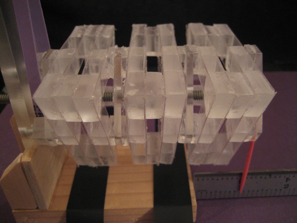
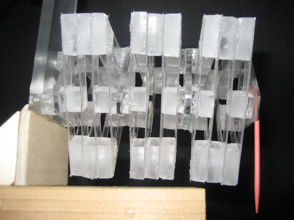
| 01:16, 25 May 2010 | ComLinMech12.jpg (file) |  |
125 KB | Compliant mechanism - end view. | 1 |
| 02:16, 25 May 2010 | CompliantMechanismFiles.zip (file) | 40 KB | pdf, dwg, and openSCAD for prototype compliant linear mechanism | 1 | |
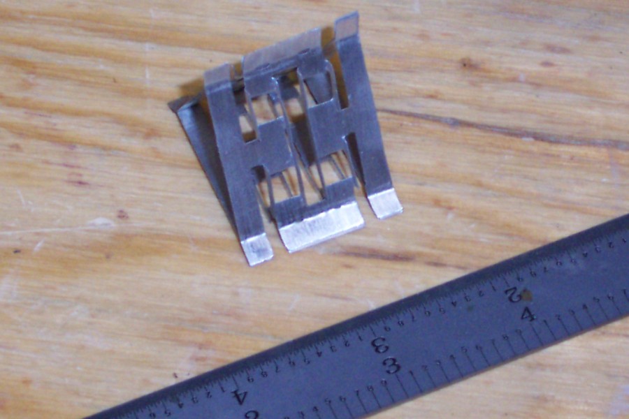
| 00:32, 31 May 2010 | EtchScriber1.jpg (file) |  |
118 KB | 1 | |
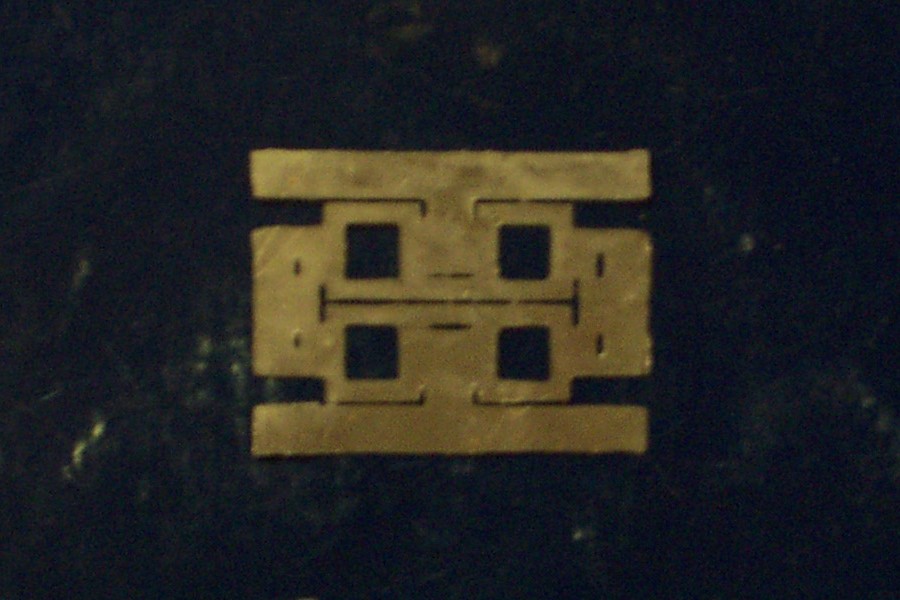
| 00:33, 31 May 2010 | EtchScriber2.jpg (file) |  |
131 KB | 1 | |
| 00:33, 31 May 2010 | EtchScriber2a.jpg (file) |  |
129 KB | 1 | |
| 00:34, 31 May 2010 | EtchScriber2b.jpg (file) |  |
135 KB | 1 | |
| 00:34, 31 May 2010 | EtchScriber3.jpg (file) |  |
131 KB | 1 | |
| 00:35, 31 May 2010 | EtchScriber4.jpg (file) |  |
144 KB | 1 | |
| 00:35, 31 May 2010 | EtchScriber5.jpg (file) |  |
168 KB | 1 | |
| 00:36, 31 May 2010 | EtchScriber6.jpg (file) |  |
143 KB | 1 | |
| 00:36, 31 May 2010 | EtchScriber7.jpg (file) |  |
152 KB | 1 | |
| 00:36, 31 May 2010 | EtchScriber8.jpg (file) |  |
121 KB | 1 | |
| 00:37, 31 May 2010 | EtchScriber9.jpg (file) |  |
110 KB | 1 | |
| 00:38, 31 May 2010 | EtchScriber11.jpg (file) |  |
97 KB | 1 | |
| 00:49, 31 May 2010 | EtchScriber10.jpg (file) |  |
103 KB | 2 | |
| 00:50, 31 May 2010 | EtchScriber12.jpg (file) |  |
98 KB | 1 | |
| 01:17, 31 May 2010 | CompliantMechanismSheetmetal.zip (file) | 11 KB | Compliant mechanism 2D sheet metal pattern in svg, pdf, and dxf formats (all generated with InkScape) | 1 | |
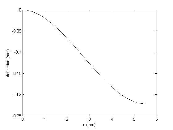
| 16:37, 7 June 2010 | BendingExample.PNG (file) |  |
34 KB | added expression for maximum deflection | 2 |
| 16:17, 12 June 2010 | ElasticCurve.png (file) |  |
4 KB | 1 | |
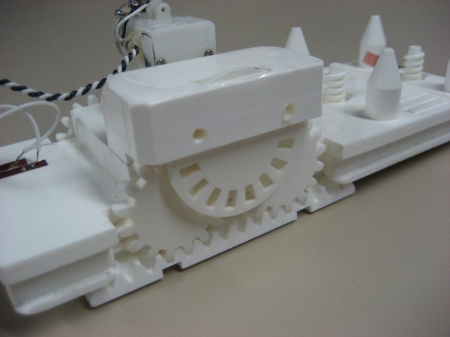
| 12:46, 18 July 2010 | Motor.jpg (file) |  |
46 KB | motor assembly with gears simultaneously meshing with rack | 1 |
| 12:48, 18 July 2010 | Multigear.zip (file) | 82 KB | This is MATLAB code that calculates center locations for two gears that are in simultaneous mesh with a third gear and a straight rack. | 1 | |
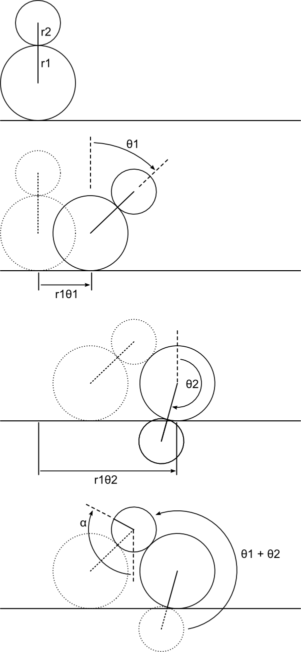
| 13:00, 18 July 2010 | AngleDefinitions.png (file) |  |
64 KB | Diagram of gear angles to accompany page on simultaneous gear meshing | 1 |
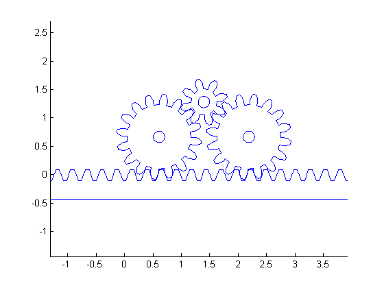
| 13:40, 18 July 2010 | TrigearsExample4.png (file) |  |
5 KB | example output of MATLAB gear center distance program | 1 |
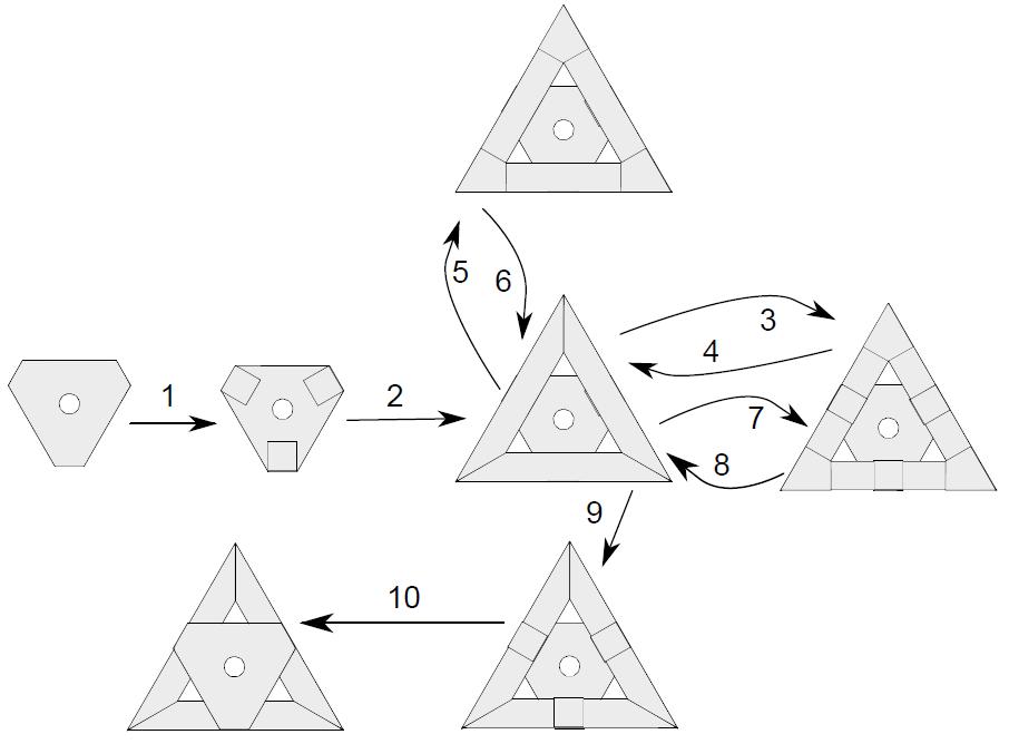
| 18:00, 21 January 2011 | PaperInstructions.JPG (file) |  |
41 KB | order of gluing operations for assembling a compliant mechanism | 1 |
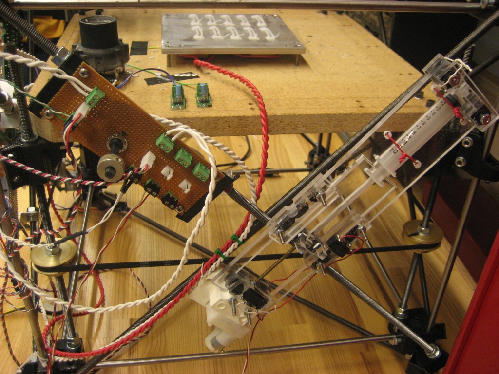
| 13:51, 22 January 2011 | MetalExtruderOverview.jpg (file) |  |
238 KB | syringe pump metal extruder overview | 1 |
| 13:54, 22 January 2011 | MetalSyringeParts.zip (file) | 75 KB | stl and dxf format CAD files for syringe pump metal extruder | 1 | |
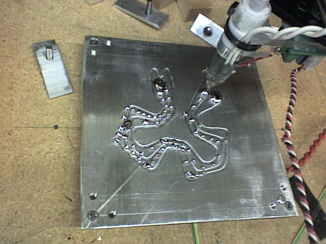
| 14:20, 22 January 2011 | Example1.jpg (file) |  |
78 KB | metal extruder test 1 | 1 |
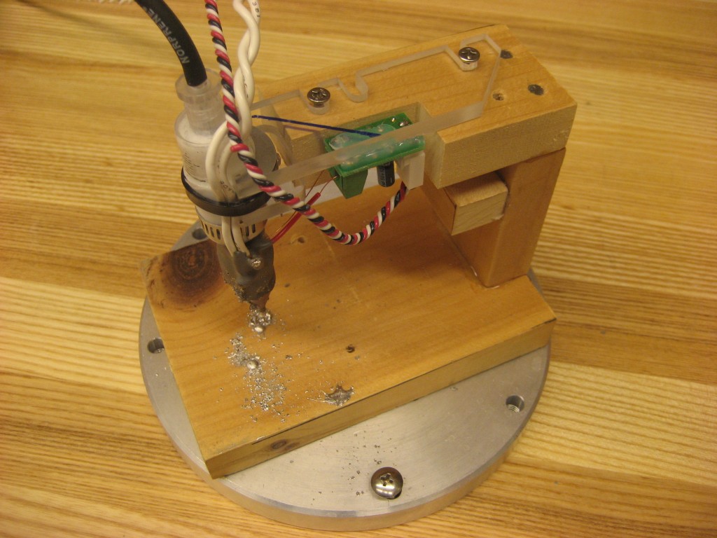
| 14:20, 22 January 2011 | Example2.JPG (file) |  |
64 KB | metal extruder test 2 | 1 |
| 14:28, 22 January 2011 | Nozzle stand.jpg (file) |  |
161 KB | 1 | |
| 14:28, 22 January 2011 | Nozzle asm2.jpg (file) |  |
158 KB | 1 | |
| 14:28, 22 January 2011 | Nozzle asm1.jpg (file) |  |
176 KB | 1 |