User:Powdermetal
Revision as of 17:16, 3 June 2016 by Powdermetal (talk | contribs)
Cycloidal Extruder Drive
Release status: Experimental
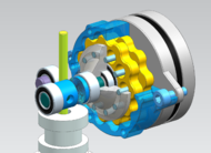
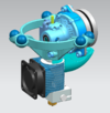
| Description | Cycloidal gearbox for a lightweight & compact direct drive extruder
|
| License | GPL
|
| Author | |
| Contributors | |
| Based-on | |
| Categories | |
| CAD Models | |
| External Link |
Contents
Intro
Running a delta printer with a Bowden-style type extruder, many people have been looking into alternatives for a more direct filament-feed response (especially when using flexible materials) while still keeping the dynamics of a lightweight effector system. There are a bunch of options out there and each one has it's specific strengths...
Project Target
- Develop a lightweight, compact and powerful direct driven extruder for drive gears like the MK8
- Utilize a NEMA8/11/14-stepper for weight reasons
- Minimize gearbox package through choosing a cycloidal drive system (gearbox ratio probably between 36:1 and 10:1)
- Potentially setup an attractive alternative to the outphased NMB PG35L-048
Build v0.3
Objective (see development history)
- Improve heat resistance - previous build failed due to material creep
- Tighten tolerance stackup for better extrusion rate precision
- Squeeze packaging
Design (see development history)
- To shorten the tolerance stackup, an additional bearing now directly centers the output shaft with the motor shaft
- Tooth clearance reduced from 0.1mm (v0.2) to 0.05mm, aiming for less waviness while keeping printability with FDM machines
- Cleaned a bug in tooth shape formula of v0.1
- Based on v0.2 results, gearbox ratio is changed to 12:1 -> no of teeth: 12, eccentricity: 1.0mm, radius: 18mm, roller radius: 2.0mm
- Some exhaust air from the hotend is directed to the stepper motor for cooling
BOM
- Printed parts from some more heat resistant material than PLA (like ABS/PETG/..., I use ColorFabb's ngen)
- 1 x StepperOnline Nema 14 .9deg Thin Stepper Motor 12.5mm 0.5A 7Ncm(10oz.in) 14HR05-0504S (50g)
- 1 x MK8 Drive Gear
- 1 x E3D v6 HotEnd - 3mm Direct (12v)
- 3 x MR105-ZZ (5x10x4mm) Ball Bearings
- 2 x MR128-ZZ (8x12x3.5mm) Ball Bearings
- 1 x MR85-ZZ (5x8x2.5mm) Ball Bearing
- 1 x 5mm Stainless Steel Precision Shaft (or a 5mm aluminium shaft from your local hardware store - make sure you go shopping with your caliper: 4.97..4.99mm is sufficient if you are on a hurry)
- 10 x DIN6325 2x10 Steel Dowel Pins
- 5 x DIN912 M2x8 Hex Socket Head Cap Screws
- 2 x DIN912 M3x8 Hex Socket Head Cap Screws
- 2 x DIN912 M3x16 Hex Socket Head Cap Screws
- 2 x Springs 0.8 x 4.7 x 15 (wire dia x outer dia x length)
- 2 x DIN912 M3x25 Hex Socket Head Cap Screws
- Ball Bearing Grease
Make & Assemble (not easy)
- Print the parts: 2 perimeters, 100% infill, layer height 0.1mm, go slowly for the gears (15mm/sec or less)
- Cleanup the gears for running smoothly before assembly - remove any blobs and strings carefully - take your time for precision later on
- Tune the excenter's bore to make it go gently (!) over the motor shaft and remove it gently again (this is still a design weakness...)
- Tune the excenter so you can assemble the MR128-ZZ bearings
- Press fit the MR128-ZZ bearings into the excenter gears, push them over the excenter
- Bolt the ring gear to the stepper motor
- Mount the excenter/excenter gears over the motor shaft as follows:
- Make the D-shaft look to the right side
- Align the marking dot of the lower gear exactly to the left side
- Align the marking dot of the upper gear exactly to the right side
- Make sure this position is kept, while the excenter and the excenter gears enter the ring gear
- Push the excenter onto the shaft until the motor shaft is max. 1.2mm above the excenter's endface (when pushing further, the excenter will start to touch the stepper motor inside the gearbox...)
- Add grease to the gears and to the holes for the pins
- Press fit the 5mm shaft into the output carrier (using the shaft-mask tool for perpendicular assembly)
- Press fit the 10 2mm dowel pins into the output carrier (the pin-mask tool and the pin-support-ring tool will help you)
- Assemble all the rest
Test & Validate
- Attached to an Azteeg X5, v1.1
- Motor current: 0.45A, 32 microsteps, 7000 steps/mm
- Retract: 0.5mm, 5mm/sec
- Speed: up to 80mm/sec, 0.4mm nozzle, 0.2mm layer height, material: PLA, temperature: 210°C
- Testing: 10x10x5 blocks, Dia30 cylinders, some larger parts, so far in summary 6 hours printing
Results
- Works - has not given up on multiple longer prints
- No lost steps while extruding and retracting during prints
- Motor temperature: approx. 50°C - the air shield seems to help
- Less waivy surface appearance than v0.2, but still not matching my Bowden setup
- No specific noise
- Loosing steps when manually extruding 5mm from the controller
- The centering-bearing needs better support on the motor shaft
- The excenter is difficult to print, to prepare and to assemble
- v0.3 objectives met
Todo
- Continue testing
- Go back to 16:1-ratio for robustness against loosing steps
- Use bearings without shields, gaining some axial space for the centering bearing for a better fit on the motor shaft
- Review some smaller issues
Links
- The development history of this thing)
- Wikipedia: Cycloidal drive
- Design of a Planetary-Cyclo-Drive Speed Reducer Cycloid Stage, Geometry, Element Analyses
- Building a Cycloidal Drive with SOLIDWORKS
- Generate DXFs of hypocycloid cams for cycloid drives
- http://forums.reprap.org/read.php?1,617389 (This engineer claims 100 grams direct extruder)
- Build v0.3 album


