Hot Rod ROBO
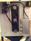
The photo at the left shows a simple stepper driver that is the basis of my distributed control system for my Hot Rod ROBO 3D printer. It features low cost components and a simple design that works well. A central transceiver chip receives and sends mono audio from/to a TRRS jack and cable leading to a computer or cell phone and transceiver the bidirectional one-pin Arduino bus. The speaker out of the driver device sends audio control signals to the Hot Rod ROBO and the microphone in line sends back audio from these stepper and heater boards. The system consists of five stepper boards as shown above, two of which contain a similar circuit designed to control the heater in response to the corresponding thermistor. One board handles the four end-stop switches. This means a total of nine ATtiny85 Arduino processors and one dual opamp circuit. That and some power transistors and many small signal transistors, a handful of resistors, and some LEDs make up the entire control electronics. So it's a simple, cost effective and straightforward way to build a 3D printer's electronics.
Wow that's some bunch of tech talk, so let's take a break and discuss why it's a "Hot Rod" before getting back into some wonderfully techie stuff. It was a chilly day in November when I sat in my one room apartment at the assisted living center and contemplated what to do about my commercial 3D printer's illnesses. It had problems with overheating, the parts fan wasn't wired up from the factory, the Z rods had no support, and the wiring harness was a real rat's nest (see photo at left). It needed a new RAMPS board, at least one of the stepper driver boards was bad, and possibly a new Arduino board, possibly not. I was looking at $200 in repairs just to get it back to it's overheating stock condition. That's when I had the first epiphany!
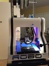
Now we all know that an epiphany is one of those "light bulb" moments when we suddenly realize something interesting or important. I personally subscribe to the view that these are divine interventions of the one true Creator interacting with us finite human creators - you may not and that's fine. Anyway, this first epiphany was not technical, it was bravado! I felt myself almost putting the pedal to the medal on a fast muscle car as I looked at the printer's two racing stripes painted black on it's white background (see image to the left). I imagined taking my printer to an auto body shop that normally works on cars and having it painted some fancy sparkly candy apple red with white racing stripes - now that would look like a hot rod printer for sure.
I got to thinking about the electronics too. Being a circuits and software skilled person, I imagined a test circuit on a breadboard with an ATtiny85 receiving commands from the computer's audio jack. An opamp would do the signal conditioning and i could generate the sounds with sample accuracy from the audio programming language Chuck. The light bulb was getting brighter and brighter - custom electronics and a slick audio control system would sure add to the hot rod nature of this printer.
It was at this point that i remembered wireframe print. A hot rod should be fast, so it should print fast as well, and the research team that came up with wire print found they could print 3D sketches of objects in on ly 8% of the time. What I would like to do is sightly different from wire print so i call it wireframe print to be more accurate. Basically I plan to print the wireframe. That is a whole other story and it is also the final hot rod aspect of this project. Now let's get back into some technology.


