Category:Mendel Rostock Development
Besides the re-design of existing there was the design of new components for Mendel Rostock (modified in Jena electronic things). With this 3D printer we present you an optimized system and show you in this article the improvements and modifications compared with the previous model.
Framework
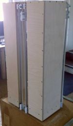
The first improvement idea of the system dealt with the framework. In order to the prevent warping of the frame, the bottom, top and side panels were strengthened. The thickness of the bottom and top plate of 12 mm were extended to 15 mm. As sidewalls 12 mm strong plates were selected. A second supporting sidewall and internal angle in the frame should also provide additional stability. The side walls serve not only the stiffening of the system but also the attachment of subsequent components such as the electronics. Figure 1 shows the modified framework from the back view.
End effector
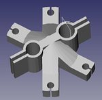
The end effector consists of penholder, platform and hotend. The penholder is the holder for the hotend in which the filament is heated and from which it will be extruded. Originally the penholder for hotend's is designed with an external diameter of 10 mm (see Figure 2).
Due to the fact, that the thermal barrier of our Hotend's has a diameter of 16 mm, the redesign of the penholder was necessary. The new penholder was designed in a way so that the old platform could be used (see Figure 3) for attachment of penholder and printer arms.
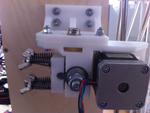
So only one component had to be redesigned. The new penholder (see Figure 4) consists of a simple plate with a hole with the size of 16 mm for the hotend. In addition, the hotend will be fixed by two horizontal introduced screws.
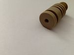
On Figure 5 a standard peek barrier will be figured.
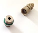
In Figure 6 the modified peek barrier for the Mendel Rostock will be displayed. In the process the standard barrier was slightly extended, in order to introduce on the top a thread.
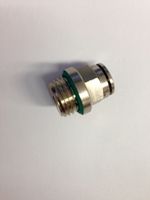
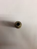
Here a metallic hose coupling is screwed (see Figure 7 & 8).
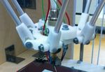
Figure 9 shows the fully assembled end-effector.
Carriages
Carriages are cars, which are located on the LM8UU camps on the silver steel shafts. Originally, they are driven by a closed belt (GT 2). We use T2.5 endless belt. Consequently, we had to use other pulleys and to larger the carriage design, in order to fix both ends of the belt. Important for the redesign, however, was the idea was to provide an opportunity, so that in the event of extension of the belt, they could tighten them. In this way, the attachment of always new timing belt should have been avoided. For this purpose an attachment is mounted to the cap, which contains the toothing of the belt as notches (see Figure 10).
Jaws
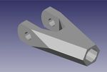
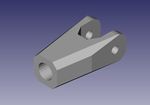
Jaws are the ends of the arms printer, are connected to one another via the arms, and end effector Carriages. These were modified and made thicker. 'Figure 11' formed from the original version.
On 'Figure 12' the modified and so more powerful version is shown.
This type of Jaws, we need, as we have decided to dispense with a purely printed printer arms and to produce aluminum rods.
Extruder
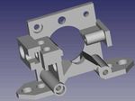
The feed unit of the extruder through which the filament is guided into the Hotend had to be redesigned. In 'Figure 13' of the initial extruder is mapped
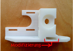
After several extrusion tests with original Rostock extruder, we found this not considered mature. For this reason we decided to change this. We modified an original Wade extruder and brought a recess in the side for Hotend out a. Here a mother is positioned, in turn, a metallic "hose coupling" is screwed. 'Figure 14' illustrates the modified Wade extruder.
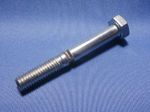
The choice of another Filamentschraube, is an innovation compared with the original. On 'Figure 15' the Filamentschraube demonstrates that we use for the Mendel Rostock.
It is the standard Filamentschraube that we mount extruder in Wade and Greg Wade. On 'Figure 16' of the modified and already built Wade extruder is ready.
Roll mounting
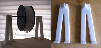
To place the Filamentrolle space as possible, the holder was mounted on top of the printer. In order to distribute the weight of non-critical, the attachment was carried out as far as possible at the edges, where the plywood the printer additionally stabilize ( 'Figure 17' ).
If you have questions about the structure or the printer function manner in detail, please contact us via 'Email' to '[email protected]' or simply 'Telephone' ' ':' +49 (0) 3641 50 96 06 '. The 'modified RP-parts 'for' Mendel Rostock 'are in 'Thingiverse' as' stl files' uploaded. The 'complete kit of parts for Mendel Rostock' is in our 'Shop' available.
Pages in category "Mendel Rostock Development"
This category contains only the following page.
