I3 Control Board assembly
|
English • العربية • български • català • čeština • Deutsch • Ελληνικά • español • فارسی • français • hrvatski • magyar • italiano • română • 日本語 • 한국어 • lietuvių • Nederlands • norsk • polski • português • русский • Türkçe • українська • 中文(中国大陆) • 中文(台灣) • עברית • azərbaycanca • |
Board assembly
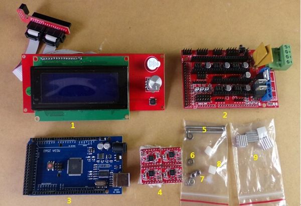
Need parts:
- 1. 1×2004 LCD
- 2. 1×RAMPS 1.4
- 3. 1×Mega 2560
- 4. 4×A4988 driver
- 5. 2×M3*30 screw
- 6. 2×M3 flat gasket
- 7. 2×M3 lock nut
- 8. 2×plastic spacer
- 9. 4×heat sink
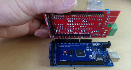
Step 1
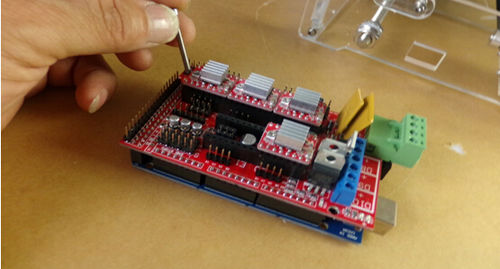
Insert RAMPS 1.4 to Mega 2560.
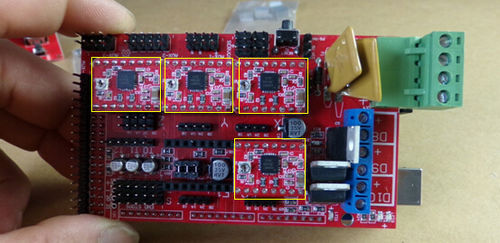
Step 2
Insert motor chip(A4988).
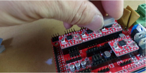
Step 3
Install the heatsink.
Step 4
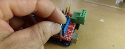
Install the M3 * 30 screws.
Step 5
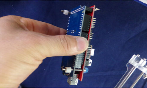
Install the plastic spacer.
Step 6
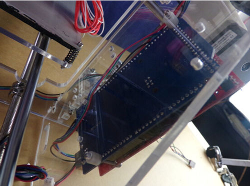
Inserted into the left side of the acrylic plate.
Step 7
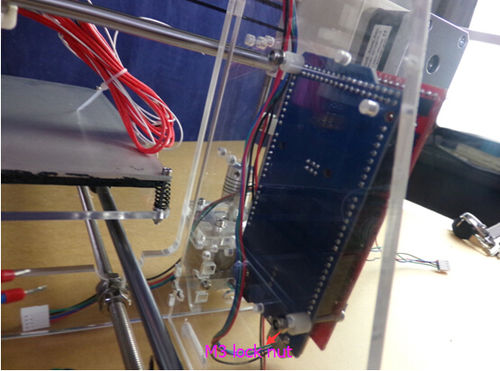
Install M3 lock nut, and tighten.
Wiring
Step 1
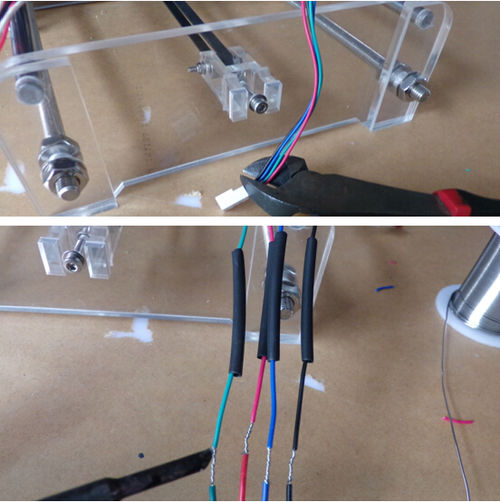
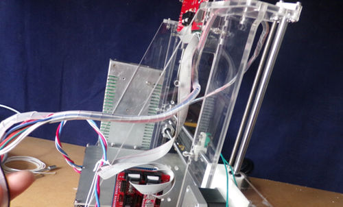
Extrusion motor wires was cut plug,, and connect 4P Dupont line and weld, the fan connect black, Red parallel lines, then and nozzle double red, double white tangled together with the tube.
Step 2
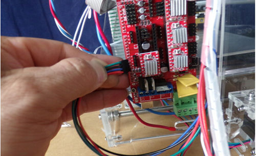
Plug the motor wires connect into EO on the control board.
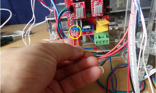
Step 3
The nozzle heat resistance double red wires connect D10.
