BrundleFab
Release status: unknown
| Description | BrundleFab - an inkjet based sugar printer
|
| License | |
| Author | |
| Contributors | |
| Based-on | [[]]
|
| Categories | |
| CAD Models | |
| External Link |
Contents
Introduction
'BrundleFab' is an attempt to build a 3D powder bed printer, using sugar as the working medium, and with output as a food quality edible.
The name comes from the 1986 movie 'The Fly': "Do you normally take coffee with your sugar?"
Current "state of the project" video: <videoflash type="youtube">zHy0NdR5VD0</videoflash>

Sources
My sources are available on GitHub:
- Powderbed design and test: https://github.com/ezrec/BrundleFab-hardware
- GCode interpreter (ATMega2560) https://github.com/ezrec/BrundleFab-firmware
- Inkjet controller (InkShield) https://github.com/ezrec/BrundleFab-printhead
- Slicer toolchain scripts https://github.com/ezrec/BrundleFab-software
Electronics
Power
I'm using a SATA connector from a PC power supply, and have soldered on 0.100" pins for easy interfacing.
SATA Power Connector

Arduino
I using steppers for my X, Z, and E axes, and the DC Motor + Encoder for the Y (printhead) axis.
There are two ATmega devices - an ATMega2560 controls the UI, GCode, and X/Z/E axes. A ATmega328 controls the printhead and Y axis, and is directly mounted on the inkbar carriage.
They are connected by a 115200n81 serial link (5v logic, not RS232).
AdaFruit 1.8" TFT Shield + Joystick
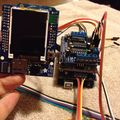
AdaFruit 1.8" TFT attached to the logic stack

Adafruit Motor Shield v2
The Adafruit Motor Shield v2 appears to be inadequate for accurate PID control of DC motors - the I2C bus latency to the PWM controller is too high for my PID tuning skills.
Adafruit Motor Shield v1
However, the Adafruit Motor Shield v1 has the Arduino PWMs directly connected to the motor drivers - I have been able to get pretty accurate PID control of my DC motors with this shield.
Although it is no longer sold by Adafruit, the design has been duplicated by a number of 2rd party manufacturers, so it's still easy to come by.
Ink Head
InkShield
I'm using Nicholas C Lewis' Inkshield device to control a HP C6602 cartridge.
Running the InkShield directly from an Arduino

HP F4480
I am using a pile of trashed HP F4480 DeskJet printers as a source of motors, gears, and encoders.
Here are some information I have discovered about the internals of this printer:
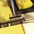
Rotary optical encoder board
This board monitors the 1200 DPI optical encoder disk attached to the main paper handling roller in the printer.
It uses quadrature encoding, and can monitor both forward and reverse direction.
I am using the 'Encoder' library from the [1] Arduino library collection.
Pin 1 is the kerf on the CPU board connection
| Pin | Function |
|---|---|
| 4 | Output A |
| 3 | Vcc 3.3v |
| 2 | Output B |
| 1 | Gnd |
Printhead Controller
The HP F4480 printhead carriage monitors a 1200 DPI optical encoder strip, which is the feedback to the carriage motor, and manages the shift registers to the matrix printhead.
These electronics will not be used by BrundleFab, and are bypassed - the IR sensor for the optical encoder is directly wired to the ATmega323.
DC Motor/Encoder Interfaces
I scavenged the connectors from the HP printers and build some extension cabling for the X and Y axis controls.

Wire colorcode key:
| Color | Function |
|---|---|
| White/Orange | Ground |
| Orange/Write | 3.3v |
| White/Blue | Encoder A |
| Blue/White | Encoder B |
| White/Purple | Motor - |
| Purple/White | Motor + |
DC Motors
Although the printhead DC motor was designed to be driven at 30v, it operates fine at 12v, PWM at 50% for nominal operation.
Fuser
The Fuser consists of a high-intensity halogen bulb (from a HP laser printer) with an aluminum foil reflector.
Temperature monitoring is very indirect, and is done by using a 250K/Beta 4066 thermistor (salvaged from the same HP laser printer), using a 1.8K resistor for voltage dividing.
After the inking pass, the intent is to run the fuser over the inked area, and lightly caramelize the colored section.
Or, at the very least, dry the ink out to prevent excessive saturation.
Powderbed
Overall Design
From the front of the printer, the X axis is from left (negative X - the feed bin area) to right (positive X - the part bin area).
Past the part bin, there is a 'cleaning' chute area where excess powder will fall during the print cycle.
The conceptual design is for the powder wipe to immediately follow the print head, and the print head never executes a negative X movement until the Z slice is complete.
The X axis is controlled by a stepper motor, which pulls on a braided (non-stretching) fishing line attached to the Y axis trolley.
The Y axis is controlled by a DC motor + linear encoder, mounted on the inkjet carriage of the HP4480 printer. As I have multiple HP4480s, I will use a mounting system that will allow me to easily interchange the inject carriage, so as to replace the Y axis movement in case of failure.
The Z-part and E-feed axes will be driven by two NEMA17 steppers, driving a 40cm trapezoidal (Tr8x4) drive screw. See the Piston section for details.
Current Progress
Powder bed frame is 100% complete:
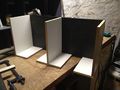
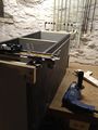
Powderbed Interior
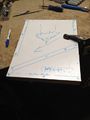
Powderbed waste chute and electronics area blueprint
Powderbed 80% complete
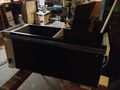
Powderbed 85% complete
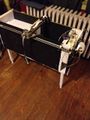
Powderbed with legs
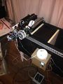
All electronics


Piston
Currently I only have NEMA 17 motors, so I have built a piston insert for half of the frame. The left side of the frame will be unused for this prototype, until I get larger stepper.
Instead of ripping the frame apart, I came up with the idea of using an insert - a divider with a base (making an inverted "T" shape) and the piston plates are on each side of the T.
The insert uses two NEMA 17 motors with integral 40cm Tr8x4 screws, 4 pieces of MDF, and some scrap sheet metal a motor mounts. The endstops, although in the same physical location, are configured differently for each axis.
For the Z axis, which starts at the top of the piston chamber and moves down, the endstop is for Maximum Z.
For the E axis, which starts at the bottom of the piston chamber and moves up, the endstop is for Minimum E.
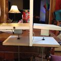
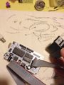
Piston insert, for the right half of the frame
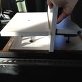
Inserting the piston insert into the right half of the frame


NOTE: This piston design jams easily on even small amounts of powder grit, and requires a high precision fit - pretty much impossible with MFD with varying humidity conditions. It is not recommended for new designs.
Print Media Material Testing
These early tests were done with 'hand printing' an object (manual layer deposition, and using a needle bottle to apply large binder droplets).
Granulated Sugar + Water
Process
- Lay down 10mm of granulated sugar
- Sift a layer of 1mm of granulated sugar
- Apply 1mm droplets of (colored) water to the granulated sugar via a needle bottle (unknown tip size)
- Go to 2. until part build volume is complete
- Lay down 10mm of granulated sugar
- Heat at 120C (250F) in oven for 1 hour
- Let cool
- Remove from build container, and remove excess sugar
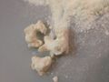
Results
The resulting object was stiff, but easily crumbled. Water dispersion through the granulated sugar had an approx 5mm radius, and substantially filled in the interior of the part (wireframe cube).

Analysis
- Droplet size should be smaller
- Either a finer granularity or pressure packing of the media should reduce the spot size of the print head
- A food safe adhesive should be tried to increase bonding strength
- In-powder adhesive (such as meringue powder) activated by water
- In-suspension adhesive (such as egg whites)
Powdered Confectionery Sugar + Water
- Lay down 10mm of granulated sugar
- Sift a layer of 2mm of granulated sugar, and pack down to 1mm.
- Apply 1mm droplets of (colored) water to the powdered sugar via a needle bottle (unknown tip size)
- Go to 2. until part build volume is complete
- Lay down 10mm of granulated sugar
- Heat at 120C (250F) in oven for 1 hour
- Let cool
- Remove from build container, and remove excess sugar
Results
Sugar did not re-crystallize, I suspect the cornstarch at fault here.
Analysis
- Powdered Confectionery Sugar is not suitable for printing, due to the cornstarch content.
Powdered Sugar/Meringue Powder + Alcohol/Water
- Powder base is granulated sugar and meringue powder
- Adhesive is alcohol and water
Procedure
- Lay down 10mm of powder
- Sift a layer of 2mm of powder, and pack down to 1mm.
- Apply 1mm droplets of (colored) adhesive to the powder via a needle bottle (unknown tip size)
- Go to 2. until part build volume is complete
- Lay down 10mm of granulated sugar
- Heat at 120C (250F) in oven for 1 hour
- Let cool
- Remove from build container, and remove excess sugar
Results
- Sugar/Meringue powder is % by mass
- Alcohol/Water is % by volume
| Sugar | Meringue Powder | Water | Alcohol | Results |
|---|---|---|---|---|
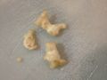
| 90% | 10% | 50% | 50% | Small droplet size (1mm), no capillary creep from the droplets; resulting object could be rinsed of excess powder |
Analysis
- Should be a sufficient working material, need to experiment with different ratios.
90%/10%+50%/50% (dry)
90%/10%+50%/50% (wet)

