Generation 2 Electronics
Contents
Generation 2 Electronics
Overview
Once you start putting electricity into your RepRap - even at just 12 volts - you have to take basic, common sense precautions to avoid fires. Just in case these fail, test your workshop smoke detector. Got no smoke detector? Get one!
Parts List
<iframe width='500' height='300' frameborder='0' src='http://spreadsheets.google.com/pub?key=pmEMxYRcQzzATwbOb71BmGA&output=html&gid=30&single=true&widget=true'></iframe>
Power Supply

The RepRap machine needs a regulated power supply giving at least 8 amps at 12 volts. The easiest way to do this is to convert a normal PC power supply into a RepRap power supply.
More info and setup instructions here.
Arduino & Arduino Clones

Arduino is an open source project that has created an easy and powerful microcontroller board. It is the brain of the RepRap electronics. You can get a premade Arduino, you can buy a kit, or you can even make it from scratch yourself. They all look the same to the rest of the electronics or to your computer.
More info and setup instructions here.
Power/Communications Card v1.3
<div class="thumb tright"></div>The Power / Communications card is the link between the computer and the RepRap printer. It uses RS232 to communicate over a serial port. If you do not have access to a serial port on your computer, there are widely available USB -> RS232 converters available. It also distributes the 12v power via connectors for all the other boards.
Signals are passed from the RS232 around the communications ring until they arrive at the device to which they are addressed, which then acts upon them. Thus the RS232 Transmit from the Communications board goes to the Receive on the first controller; that board's Transmit goes to the next board's Receive.
More info and build instructions here.
Stepper Motor Driver v1.1
<div class="thumb tright"></div>Each stepper driver board drives one of the stepper motors. You need three of these boards for a fully functioning RepRap. Each board controls the position of one axis. Together, they position the print head anywhere in the 3 dimensional build area.
More info and build instructions here.
DC Motor Driver v1.0
<div class="thumb tright"></div>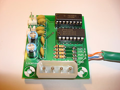
This board is capable of controlling two low current DC Motors in both forward and reverse. It has a speed/direction interface and is easy to control.
More info and build instructions here.
PWM Driver v1.0
<div class="thumb tright"></div>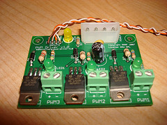
This board is capable of driving medium DC loads with TIP120 power transistors. It has a PWM interface and is also easy to control.
More info and build instructions here.
Opto Endstop v1.0
<div class="thumb tright"></div>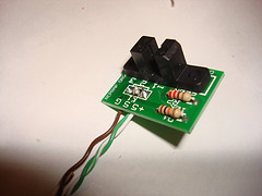
All of a RepRap's axes all need a datum (also known as home position or end-stop) to reference their movements. At the start of each build each axis needs to back up until the datum point is reached. We use one opto-switch for each axis to define its position. This page tells you how to wire one up.
More info and build instructions here.
Temperature Sensor v1.0
<div class="thumb tright"></div>
This sensor allows you to read a thermistor as an analog value. It is a very small and simple helper board.
More info and build instructions here.
Wire it Up!
Now that all the boards are created, you'll need to wire it all up.
First, find or cut a flat piece of thin plywood, about 12" x 12".
Next, place all your boards on the wood in a layout similar to the one shown on the right. Mark with a pencil through each hole, and also optionally around each board for drill holes and as a board outline.
Then, take all the boards off and drill out each drill mark with a 1/8" (or 3mm) drill bit.
Take a foot or so of silicon aquarium tubing and cut short (1/4") lengths of it. You will be using these to mount the boards to the wood.
Now, mount each board on to the wood with M3 x 15mm bolts. Use washers on both sides, and use a short piece of tubing between the board and the wood for spacing (and shock absorbtion). Tighten down the nut by hand, and then a little bit with pliers or a wrench. It should be solidly attached, but not wrenched down too much.
Once you have the boards mounted, wire them up according to the diagram below. If you wired up the boards according to the directions, you can simply follow the colors. Otherwise, you'll need to make sure the pins match up.