Wood-D
This page is a development stub. Please enhance this page by adding information, cad files, nice big images, and well structured data!
Release status: experimental
| Description | Just another wooden 3D-Delta-Printer (Open Source Project)
|
| License | CC BY-NC-SA 4.0
|
| Author | |
| Contributors | |
| Based-on | [[]]
|
| Categories | |
| CAD Models | CorelDraw / PDF
|
| External Link |
Contents
Description
Wood-D - Just another wooden 3D-Delta-Printer (Open Source Project)
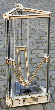
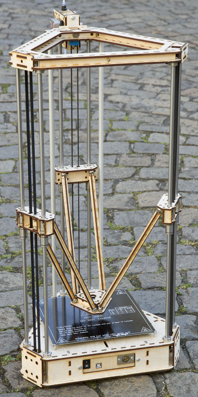
Wood-D is a 3D-Delta-Printer based on LASER-cut plywood or MDF. The joints are made of bearing balls and neodym ring magnets.
Design Objectives
Main Features
- Large printing area while compact dimensions.
- All constructed parts are made of 4 mm LASER cut plywood or MDF
- High precision of part positions, mounting angles and fitting based on LASER cut design.
- Easy assembly! The plywood parts/puzzle are held together with key and slots and a little bit of glue. Plug and play nearly without measuring or adjusting.
- High stiffness due to box design with cross bracing.
- All non-plywood parts are standard industrial parts, which can be bought in online shops or eBay. (only drive shafts have to be sawed).
- Magnetic joints simplify the construction by giving a very high precision, automatic readjustment, less friction and zero backlash.
- Prepared for PCB Heatbed (200 x 200 mm) or disk Heatbed (250 mm)(3 point leveling).
- Effector is prepared for J Head Nozzle (or others with 16 mm mounting diameter).
- Effector with fan (25 mm) and air channels for nozzle cooling.
- Electronics placed in a drawer for easy service and adaption. The drawer has mounting holes and slots for most common electronics.
- Mechanical OR optical Endstops
- All cables can be hidden in base/top box and 2 cable tubes.
- Sub-D connector in top box for HotEnd and extruder drive.
- Mounting place for bowden extruder dive (cold end)
- Necessary tools: LASER cutter (visit a FabLab/Hackerspace in your area), hand saw and file for metal, screw drivers, inbus keys, gripper, cutter, soldering iron, casein glue, 2-component glue (Epoxy)
Optional Features
The plywood parts already have mounting holes for additional / optional features:
- Auto bed leveling
- 24 LED in top box to light the printing area.
- 24 (12, 8, 6, ...) LED ring below the effector to light the actual printing (not in combination with Auto bed leveling).
- 13 (9, 7, 5, ...) LED half ring below the effector to light the actual printing. (in combination with Auto bed leveling)
- Fans in base box (40 mm)
- LCD panel box (at work...)
- 3 pedestals with 8 mm threads
- Alternative effector designs for other nozzles are available.
Specifications
| Principle | Delta / Rostock | |
| Construction | LASER cut 4mm plywood or MDF (5 pieces a 400 x 300 mm) | |
| Printing area | Rectangle 200 x 175 mm or Circle 240 mm diameter or ... |
See next chapter |
| Printing height | 225 mm (Beta 1) 280 mm (Beta 2) |
(Beta 1: at a linear system length of 650 mm) (Beta 2: at a linear system length of 700 mm) about linear system length minus 425 mm |
| Dimension base box | 337 x 296 x 60 mm | |
| Dimension top box | 337 x 296 x 20 mm | |
| Dimension printer | 337 x 296(+extruder drive) x ~750 mm | Height depends only on linear system length |
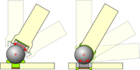
| Joints | Magnetic (neodym ring magnets with bearing balls) | |
| Drive | NEMA 17 Stepper motors with timing (cam) belt GT2 or T2.5 |
Printing Area / Space
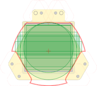
In contrast to a cartesian printer (X-, Y-, Z-axis) with a fixed rectangular printing area (X, Y) you can decide which ugly compromise you will choose for a delta printer. The different printing areas affects only the settings in firmware and software - no hardware change required. The reachable area at a delta printer is an intersection of circles and cut-offs by mechanical limits. Maybe future CAM software can handle this reaching area as printing area.
| Geometry | Size | X min | X max | Y min | Y max | Y Offset | PCB Heat Bed | Centered to | Comment |
|---|---|---|---|---|---|---|---|---|---|
| Circle | Dia. 240 mm | -120 | 120 | -120 | 120 | 0 | Outside | System | |
| Circle | Dia. 210 mm | -105 | 105 | -90 | 120 | 15 | Inside | PCB HeatBed | |
| Square | 186 x 186 mm | -93 | 93 | -87 | 108 | 15 | Inside | PCB HeatBed | |
| Rectange | 200 x 175 mm | -100 | 100 | -66 | 109 | 21.5 | Inside | - | |
| Rectange | 240 x 110 mm | -120 | 120 | -30 | 80 | 25 | Outside | - | |
| Rectange | 255 x 85 mm | -127.5 | 127.5 | -17.5 | 67.5 | 25 | Outside | - | |
| Rectange | 260 x 75 mm | -130 | 130 | -12.5 | 62.5 | 25 | Outside | - | |
| Rectange | 280 x 42 mm | -140 | 140 | -1 | 41 | 20 | Outside | - | |
| SAVE Circle | Dia. 228 mm | -114 | 114 | -114 | 114 | 0 | Outside | System | Pos. Joint rot. Angles |
| SAVE Square | 180 x 180 mm | -90 | 90 | -68 | 112 | 22 | Inside | - | Pos. Joint rot. Angles |
In Z-direction the printing space is (for easy handling) an extrusion of the printing area (cylinder, cube). You can get a little more printing height by shrinking the area. The printing height depends direct on the drive shaft length (1 mm more shaft gets 1 mm more height). For more details see spreadsheet on GitHub repository.
'SAVE' means that the joints rotation angles are only positive. On negative rotation angles the effector drives below the lift - this can be handled by the firmwares math but needs room for the joints and diagonal rods.
Parts
Constructive Parts
Base and Top Box
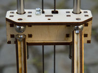
The base and top boxes are made of LASER cut plywood and hold together with key and slots and a little bit of glue. Through the box design with cross bracing the stiffness is very high. All holders, fittings, slots… are part of the LASER cut design.
Linear System
Beta 1: Standard industrial linear system with a 8 mm drive shafts and linear bearings LM8UU
Beta 2: Standard industrial linear system with a 12 mm drive shafts and linear bearings LM12LUU
The printing height depends on the length of the shafts. 100 mm more shaft gives 100 mm more printing room but also more instability.
Lift (vertical carriage)
TBD
Effector (3D carriage, holder of the nozzle)
TBD
Weight of Effector:
| Part | Weight [g] |
|---|---|
| Wooden Box + Screws | 40 |
| 6 Balls | 42 |
| 6 Magnets | 8 |
| J Head Nozzle (mk5) + Bowden Conn. | 30 |
| Fan | 5 |
| R/C Servo + Leveling Switch (optional) | 30 |
| SUM | 155 |
Joints
Magnetic joints made by neodym ring magnets (10 x 6 x 3…4 mm [outer diameter x inner diameter x height]) and bearing balls (12 mm [diameter]).
Beta 1: The bearing balls are glued to the lift (carriage) and effector. The ring magnets are part of the rods.
Beta 2: The ring magnets are pressed in and glued to the lift (carriage) and effector. The bearing balls are part of the rods.
See also article Joints for Delta Printer and Magnet joint
With the combination of a ring magnets 10 x 6 x 3 mm and bearing balls (12 mm) a cracking force of about 5.5 N (550 g) upright was measured. The magnets datasheet promises a holding force of 1.5 kg at a big and flat piece of steel.
Mounting Places
Mounting place for bowden extruder dive (cold end)
- Wood-D Extruder Drive
- Others by adding a bracket.
Drive Parts
Motors
Three standard NEMA 17 Stepper motors are used. The length is not limited
Recommended torque: more than 0.4 Nm (44 Ncm)
Timing (Cam) Belt and Pulleys
Standard industrial timing (cam) belt type GT2 with a 20 tooth pulley OR type T2.5 with a 16 tooth pulley. Clamp plates are part of the LASER cuts for both types.
Spanning can be done by shifting downwards the motor (up to 3 mm) while tighten screws.
Electronics
Electronics placed in a ‘drawer’ for easy service. The drawer has mounting holes and slots for:
- Arduino Due with RADDS (recommended)
- Arduino Mega 2560 with RAMPS 1.4
- Megatronics
- Generation 7 Electronics
- Sanguinololu
- RUMBA (overlapping PCB)
- Any other electronic (max. 130 x 105 mm). Only change the front plate of the drawer.
Additional mounting holes inside base box for:
Or any electronics compliant with RepRap Interface Standard RIS 1 with DIY mounting or external case. See List of electronics
Used in Beta 1: Arduino Mega 2560 with RAMPS 1.4 shield and Marlin firmware
Used in Beta 2: Arduino Due with RADDS shield and Repetier-Firmware
The base box gives enough room for hide the board and all cables. For the wiring between the base and top box two aluminum tubes holds (and hides) the cables.
EndStops
Endstop switches mounted in top box can be chosen from the following list:
- Micro switch with 19 mm length. Can be clamp in with a M3 screw.
- Transmissive optical sensor with phototransistor CNY 37 or TCST 2103
- Endstop PCB for optical sensor like Gen7 Endstop 1.3.1
Fine leveling can be done by M3 screws in the lifts
Cabeling
TBD
Auto Bed Leveling
TBD
Printing Parts
Extruder Nozzle
A standard J Head Nozzle is used. See also RepRap Interface Standard RIS 1 for nozzle holder.
Bowden Extruder Drive
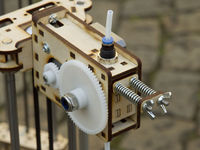
The extruder drive case is also LASER cut and is related to the Wade's Geared Extruder.
The details are described in the separate article Wood-D Extruder Drive.
Heated Bed
The base box is designed to hold a standard square PCB Heatbed (active area 186x186mm). Alternatively a disk with a diameter up to 300mm can be used (active area diameter 240mm).
The square heated bed is shifted 15 mm in +Y direction to reach the corners and get a bigger print area.
Three long holes are available for own disk bed design. Beta 2: Additional three magnets can be pressed in to hold a bed.
Note: Aluminum disks and round mirrors with 250 mm diameter are available in online shops and eBay.
Additional Parts (Option)
LED illumination
TBD
LCD Panel
TBD
Bill of Materials
>>> PRELIMINARY<<<
- # Parts
- 5 4 mm plywood or MDF with 400 x 300 mm
- 3 Steel shaft 12 mm with length 700 mm (grounded surface and hardened)
- 6 Long linear bearing for 12 mm LM12LUU
- 2 Aluminum tube 16 mm with length 640 mm
- 6 Ball Bearing with flange F605ZZ
- 3 Steel shaft 5 mm with length 34 mm
- 3 Timing (cam) belt GT2 or T2.5 with length about 2 m
- 6 Pulley for GT2 (20 teeth) OR T2.5 (16 teeth)
- 3 NEMA 17 Stepper Motor
- 12 Screws M3 x 8
- 12 Washer M3
- 12 Bearing balls 12 mm
- 12 Neodym ring magnets 10 x 6 x 3…4 mm
- 1 PCB Heatbed OR self-made disk bed
- ? Screws and springs for heated bed
- 1 Thermistor
- 3 Endstop switch OR optical sensor OR …
- ? Screws and springs for end switch
- 1 Controller unit with stepper driver (Arduino+RAMPS, Gen7, Megatronics, Sanguinololu…)
- 1..2 Fan 40 x 40 x 20 mm, 12 V
- 1 Fan 25 x 25 x 10 mm, 12 V
- 1 Power supply
- 1 Power switch
- 1 Extruder HotEnd (J-Head-nozzle mk5)
- 1 Extruder drive (Wood-D Extruder Drive)
- 1 PTFE (Teflon™) 4/2 mm tubewith length about 1 m
- ...to be completed…
- Casein Glue
- 2-Component Glue (Epoxy)
Downloads
After finishing the first beta phase the construction drawings and LASER cut files will go online. Please wait...
Design and LASER cut files at GitHub repository github.com/jkDesignDE/Wood-D
Current Status
Beta 1:
| Part | Status | Comment |
|---|---|---|
| Dimensions Drawing | ready | at GitHub repository github.com/jkDesignDE/Wood-D |
| Constructive and drive parts | ready | Improvements in Beta 2 |
| Joints | ready and working | Improvements in Beta 2 |
| Printing parts | ready | |
| Electronics RAMPS | ready | |
| Electronics RADDS | rewirering, testing... | |
| Motor Driver | PROBLEMS, still testing... | Switched back from DRV8825 to A4988, |
| First print | ... |
Beta 2:
| Part | Status | Comment |
|---|---|---|
| Dimensions Drawing | ready, but still improving | at GitHub repository github.com/jkDesignDE/Wood-D |
| Excel Movement and Joints Calculation | ready | see SpreadSheet Leveling (SSL) for Delta Printer |
| Redesign of all wooden parts | ready, optimizing puzzle arangement | |
| Other parts power supply, filament spanner |
most ready, some at work... | |
| LASER cut | waiting... | |
| Verify build | ... | |
| Publishing design | ... | |
| Totorials | ... | |
| Improvements | ... |
Sub-Projects
See also sub-project:
- Wood-D Extruder Drive
- LCD Panel 20 x 4 Character (coming soon…)
- Filament Spanner (coming soon…)
- Filament Clamp Stand (coming soon…)
- SpreadSheet Leveling (SSL) for Delta Printer (File:Delta Printer Spread Sheet Leveling.ods)
Links
More infos about the project on the blog page wood-d.de (German language)
