Wallace Build Manual
--MrJohn 01:20, 3 February 2012 (UTC)
This build is based on my build of the Wallace and will require some editing as the machine changes. Feel free to make changes where needed just add your signature by adding the 4 ~ marks to date and time stamp.
Photos and video coming soon!
Contents
Dimensions
The rod dimensions can be automatically calculated by the OpenSCAD code in the v1 branch from the GitHub repository:
git clone -b v1 https://github.com/whosawhatsis/RepRap-Wallace.git
For a build volume of 200x200x95 this gives:
Parsing design (AST generation)...
Compiling design (CSG Tree generation)...
ECHO: "X rod length: ", 350.5
ECHO: "Y rod length: ", 282
ECHO: "Z rod length: ", 275.1694173824159
ECHO: "foot rod length: ", 211.5
ECHO: "leadscrew length: ", 175.1694173824159
ECHO: "base rod length: ", 334.5
ECHO: "top rod length: ", 318.5
...
- Overall, a 200x200x95 build volume may require 2x 36" smooth rods 2*(350+282+275)/25.4=2*35.7" and 2x 36" threaded rods, (((211.5+175.16)*2+318.5+334.5)/25.4=56.15").
Assembly
- Overview of the RepRap Wallace
- See also at 2PrintBeta: Build Wallace, good description (maybe sync the description with this page)
X Axis
X Carriage
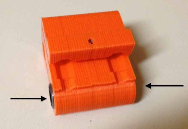
- Insert the 3 linear bearings into the X carriage, by placing each bearing into the bore and then flipping the carriage over and pressing the bearing against a firm but soft surface until the bearing is nearly completely inside the bore. They are meant to fit tightly, but if they will not fit, use a screwdriver to gently flex the plastic out and press the bearing in.
- Set the X Carriage aside.
X End Idler (Left Side)
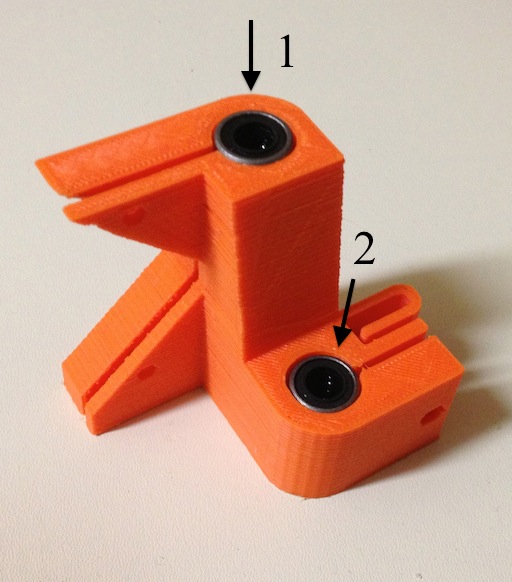
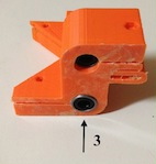
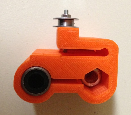
- Insert two (2) bearings into the bore (one from each side)
- Insert one (1) hex nut into the hex bore.
- One end is too small for the hex nut; this is the top of the X Idler. Insert the hex nut from the opposite side (the bottom).
- The hex nut should move freely in the Z direction (up and down) but not rotate within the hex bore.
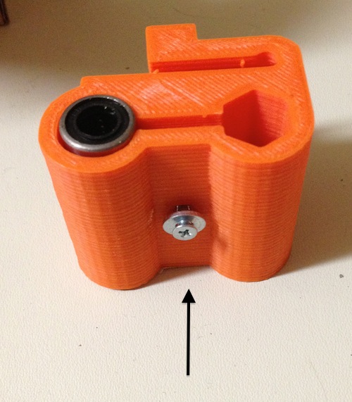
- Use one (1) M3 50 bolt and washer; insert it into the front of the X Idler (the side with the two rounded walls, not the side with the long vertical block).
- On the back, place one (1) M3 washer and install one (1) 623 bearing.
- Place another M3 washer on the bolt and finish with one (1) hex nut, nyloc nut, or a wing nut.
- Set the X Idler aside.
- (Instead of the pictured washer-bearing sandwich, DaveX used one of the dual-bearing idler pulley (same as in the y-idler assembly below.) The crown in the printed idler pulleys make the belts self-centering, perhaps reducing friction and side-fraying of the belt, while the diameter of the idler pulleys make the belt run parallel to the motion of the x-axis motion. See right side of File:WallaceDaveX20120218-Yneg.JPG for detail.)
X End Idler / Motor Mount (Right Side)
- Insert two (2) bearings into the bore (one from each side)
- Insert one (1) hex nut into the hex bore.
- One end is too small for the hex nut; this is the top of the X Idler. Insert the hex nut from the opposite side (the bottom).
- The hex nut should move freely in the Z direction (up and down) but not rotate within the hex bore.
- Use one (1) M3 50 bolt and washer; insert it into the front of the X Idler (the side with the two rounded walls, not the side with the long vertical block).
- On the back, place one (1) M3 washer and install one (1) 623 bearing.
- Place another M3 washer on the bolt and finish with one (1) hex nut, nyloc nut, or a wing nut.
- Mount the motor to the block through the provided slots.
- Tighten the motor to the mount with M3 5 or M3 10
- You may need to add extra M3 washers to take up the extra bolt length.
- Install your choice of belt pulley to the motor shaft.
- Tighten the pulley with a set screw.
Combine the X Axis parts
- Press two (2) smooth rods into the X End Idler (Left Side)
- Ensure they are tight to outside wall.
- Gently tighten the through bolt until the rods are secure.
- Attempt to rotate the smooth rod and gently pull them away from the part to ensure they are secure.
- Stand the X End Idler up
- Bolt head side facing you and with the part on the left with the rods extending to the right.
- Take the X Carriage and hold it with the two triangle points facing you and elevated.
- Slide the X Carriage on to the smooth rods from the right side.
- Slide the X End Motor Mount (Right Side) on to the smooth rods.
- Press two (2) smooth rods into the X End Motor Mount (Right Side)
- Ensure they are tight to outside wall.
- Gently tighten the through bolt until the rods are secure.
- Attempt to rotate the smooth rod and gently pull them away from the part to ensure they are secure.
- Install the belt onto the X Carriage and loop it around under X End Idler (Left Side)
- Bring the belt back over the top of the idler bearing and across to the top the X Motor pulley.
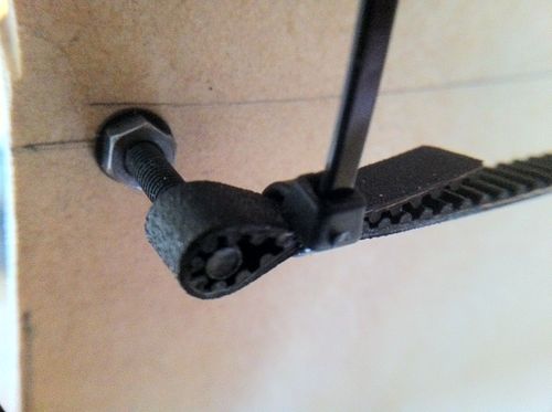
- Bring the belt under the X Motor pulley and secure it to the start of the belt. See http://www.thingiverse.com/image:90386 for a picture.
- The X Axis is complete.
Z Axis
- Take a base component and install the Z rod set screws. (Same process for both bases)
- Use two (2) M3 hex nuts; place them inside the large hex openings on the opposite side of where they will be placed.
- Insert M3 x 10 bolts through the outside of the hex nut set screws and tighten down.
- This will seat the set screw into its countersunk place.
- Loosen the M3x10 set screws until they are flush with the outside of the hex nut.
- Insert the Z smooth rod into the Z rod bore on the base.
- Tighten the set screws gently until no wiggle or endplay exists. [Can we get a general torque value for this please?]
- Secure with M3 nuts and washers. [Where? There's no obvious place to put washers and nuts on these screws, other than the countersunk nuts. Bushing 03:22, 20 June 2012 (UTC)]
- Prepare to install the Z couplings.
- On the side of the Z coupling with a small bore place an M3 nut inside against the flat surface.
- It should not rotate.
- Place the coupling on the motor shaft and press until shaft is flush with the bottom of the hex nut area on top.
- Use an M3x10 bolt as a set screw and tighten down the bolt as it passes through the hex nut and presses against a flat filed onto the motor shaft.
- Set the motor now with a coupling aside.
- Prepare the Z threaded rod.
- Take the Z threaded rod and thread two (2) hex nuts OR one Nylock nut onto the bottom of the rod.
- If using two hexes, secure the one closest to the end flush with the bottom of the rod and tighten the other against the bottom one.
- This will lock the nuts against each other and not allow them to rotate.
- Set the Z rods aside
- If using two hexes, secure the one closest to the end flush with the bottom of the rod and tighten the other against the bottom one.
- Take the Z threaded rod and thread two (2) hex nuts OR one Nylock nut onto the bottom of the rod.
Y Axis
- Take the Y Bearing idler and install the 623 bearings onto it .[I’m still unsure how this will be done, someone else that
understands, please edit this step (Two bearings press into the Y idler pulleys, one each side of the pulley, and then idler pulley assemblies mount onto the Y idler arm with M3x25 bolts using the nested M3 nuts. DaveX 20:18, 6 February 2012 (UTC))]
- Take the two (2) threaded base rods.
- They should be a bit longer than the entire X axis, (perhaps 10mm shorter than the smooth x-rods.)
- Slide the Y pulley idler onto the two threaded rods.
- Install a washer and nut on each threaded rod on each side from both directions.
- Place two (2) linear bearings on each base in the groove provided.
- Place the bearing retainers over the bearings and thread a M3 bolt and washer through to where the motors will go.
- Install the Y Motor with belt pulley installed
- Tighten using the bolts from the bearing retainers.
- Thread one (1) hex nut and one (1) washer on the ends of each threaded rod. (Both ends)
- Install the two (2) base on each end of the threaded rods
- Install washers and nut on the outside of the bases
- Secure all the bases’ hex nuts.
- Take two (2) Y smooth rods and insert them into the now secured linear bearing pairs. Ensure the Y rods are parallel to each other and perpendicular to the x-threaded rods by adjusting the bases' hex nuts.
- Install the bed mounts with M3 bolts long enough to reach through the bottom bed plate.
Mount the print bed.
- Using a flat material cut to the size you need bolt the Y rod bed mounts to the bed and secure tightly. (For a NEMA14/6mm build, the clearance between the Z-smooth rods is about 70mm less than the length of the x-smooth rods: 200mm X travel uses ~ 375mm smooth rods, and has ~305mm between the Z-bars DaveX 17:16, 8 February 2012 (UTC))
- Install bolts in the middle of the bed on each end, forward and aft.
- From top to bottom should be Bolt head/washer/bed/washer/nylock nut
- Thread the Y belt through the Y Idler bearing around the Y Motor Pulley back to the other Y bearing Pulley and to the other end of the print bed.
- Secure the ends of the Y belt to the bolts at the ends of the print bed.
- Loosen the Y Idler and pull the Y belt gently.
- Re-secure the belt on one end of the print bed.
- Tighten the Y Idler until it is in line with the two bolts securing the end of the belt.
- There should be no pulling left or right when the print bed is moved. It is essential that the line of the belt is perfectly straight on both ends.
Bringing the X Y and Z together.
- Take the X axis and thread the Z threaded rods through the bottom of the X ends capture nuts. (Both Sides)
- Ensure you have the X right side up, the hex nuts will not hold the X axis up if it is upside down.
- Thread the Z rods until about 50mm is left on the bottom.
- Gently lift the X Axis up by the Z threaded rods and guide the Z Smooth rods into the two linear bearings on the X Axis.
- Lower the X Axis until the bottom of the Z threaded rods meet the Z motor couplings.
- Gently press the hex nuts into the Z motor couplings.
- They should fit snug but not rotate within the space.
- They are designed to prevent damage when the nozzle crashes into the bed. (In theory they will pull away)
- Attach the Z top clamps to the top threaded bar with 4 M6 nuts and 4 washers. Slip the assembly over the tops of the Z Smooth rod and adjust such that the Z Smooth rods are parallel.
This should complete structural build.
- You will still have to wire the electronics, install an extruder and heated print bed if desired.
--MrJohn 01:20, 3 February 2012 (UTC)
Note: When building the Nema17/8mm version you might find yourself in a situation where the hotend is to short for the X-carriage. I resorted to modifying the extruder to let the hotend stick out further.
-- rkoeppl 02:00, 28 March 2012 (UTC)
