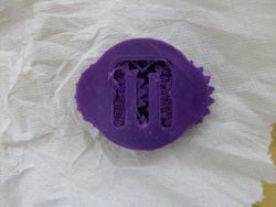
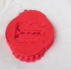
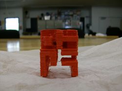
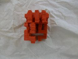
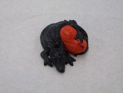
User:Vincenticart
Vincent Icart RepRap Wiki
| RepRap User: Vincent Icart | |
|---|---|
| University | Penn State |
| Class of | Summer Internship 2014 |
| Major | General Engineering, École Centrale de Marseille [1] |
Contents
About
The purpose of my internship is to do research on open-source 3D printing. I was involved in a Fablab in my university back in France where we used an Ultimaker and CubeX Duo. I didn't have any hands on experience on Repraps before arriving here, so the first weeks were dedicated to understand and get confortable with the use of these machines. Then, I could start trying to fix the different machines in the lab along by working on anxiliary projects. Below are the main progresses on the printers.
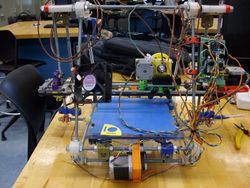
Rainbow
Rainbow was close from working when I got here. Here is a list of the most important works done on the printer:
- Equipped with the fan.
- Reflashing the arduino as connection issues were experienced.
- Calibration.
- Squarring of the frame.
- Removing and putting back on the extruder as it was clogged, and rewiring of the hot tip as a short kept triggering a "Max temperature" reached while printing.
The printer is now printing well, although the calibration part shows that best results could be acquired if the axis were squarred more accurately. Besides, on some specific areas, the infill doesn't reach the perimeters.
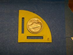
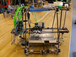
McDonalds
This printer required some work to get it back working.
- There was a lot of slack for the carriage which could rotate a little around the Z axis. Actually, a all new carriage was printed. Also, the long arm was printed with a new version of the file. The new version is the same as the old one, except that the four or five last layers that made the middle of the part higher where cut. This new version can be found here Media:OpenX_arm45_F_cut.STL. This allows a tighter assembly to the main part of the carriage around the rod. This way the slack issue was fixed. As the carriage was removed, this was also the occasion to add a heat exchanger on the carriage.
- The bed was replaced by a polycarbonate one in order to prevent warpage issues. This allows better print results as first layers stick better to this kind of beds.
- X and Z axes motor drivers were replaced.
- Squarring of the frame and calibration of X axis (multiplication factor: 1.039).
- The hot tip had to be undone and the rewired, in an attempt to tighten the end of the hot tip as there was a PLA leakage during prints.
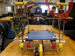
Beta
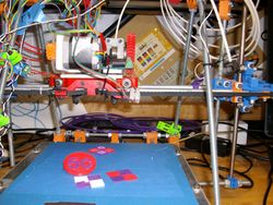
Beta was already assembled and fully equipped. However, the X axis was wobbling more than what could be fixed in this configuration with wooden parts. It was then decided to replace this X axis mounting by the PLA one used on all of our other printers.
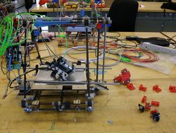
Below is a picture of the printer under construction on July, 11th.
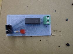
3D printed boards
Dual Extrusion
The Dual extruder was close to working when I got here and dual calibration cubes had already printed a few times. T0 extruder had to be rewired, and both extruders are now working well. However, the thermocouple boards should be handle with a lot of care as they seem to be very sensitive (especially T0) and tend to induce "Max temp." errors. New designs could be of good help in that matter as the carriage is very busy and one of the board is in the air.
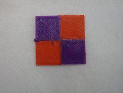
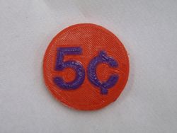
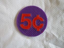
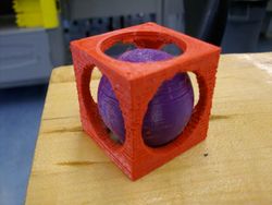
After running some test, the correct setting for the X offset between the two nozzles is 59.5 mm: extruder 0 (right one) is set as the origin, and extruder 1 (left one) is set with the 59.5 mm X offset is Sclic3r. This could be implemented in the firmware, but it is interesting to have it set this way in Slic3r as it allows to display the two different part of the assembly seperated in Pronterface or Repetier. Below are dual PLA parts we have printed:
Below are the ZIP archives with the files necessary for these prints:
| Item | Description | File Link |
|---|---|---|
| Dual Calibration cubes | Contains the two STL files and the AMF assembly | Media:Test Cube.zip |
| Dual extrusion calibration part | Contains the two STL files and the AMF assembly | Media:Plastic_Nickel_Dualstruder_Edition.zip |
| Dual ball in cube | Contains the two STL files and the AMF assembly | Media:Dualstrusion_Ball_in_Cube.zip |
Slicing
This paragraph will detail the settings used in Slic3r for our dual extrusion prints, but first it is necessery to merge the two seperate files into one assembly. Under "File", select "Combine multi-material STL files..." and select the required files, when this is done click "Cancel" and a window will pop-up to save the new file (.amf). Choose first the file you want to be affected to the first (default) extruder, then the other one will be affected to the other extruder. This new .amf file can now be opened with Slic3r. It is possible to click on "View" in order to make sure the assembly has been done correctly.
We will now explain our settings for Slic3r.
Under "Speed", make sure the acceleration parameters are set at low values. Dual extruders carriages are often heavier, and 500 mm/s² sounds like a good parameter for all accelerations on our printer.
Under "Multiple extruders", "Ooze prevention" you can tick the box in order to cool down the extruder that is idling when the other is printing. This also presents the advantage of building a skirt around the part that will act as a wiper which is very useful. Note that the skirt will be printed with the first extruder. However, with this option you might need to edit the Gcode. Indeed, the temperatures changes are made with "M109" instructions and a lot of time can be lost when the printer is waiting for the target temperature to be reached. Inserting a delay can be a better solution. If this option is not always to be used with PLA, experiments with PVA (for printing parts with disolvable support) show that is necessary as it oozes more easily. In this case, to gain time, it is possible to edit the Gcode so that the change in temperature is only set for one of the extruders. These Gcode editions will be detailed in the next paragraph.
Printer settings
Under "Extruder 1/2", tick "Retract on layer change" and "Wipe while retracting". Under "Retraction when tool is disabled", good settings for our printer with PLA seem to be respectively 5 mm and 0 mm. When PVA is used, those parameters should be investigated as this material oozes more easily.
Under "Extruder 2", set the X offset to 59.5 mm.
Editing the Gcode
The temperature changes are made with "M109" instructions. This instruction waits for the temperature to be reached. On the printer used, this instruction had to be modified as there were instabilities in temperature readings that prevented the instruction from being processed quickly. Implementing a delay can be a better solution. Notepad++ is a text editor that can be downloaded in order to make the G-code changes. First, the printing temperatures must be set. With the option "Find", search for “T0 G92 E0 M109 Sxxx ; wait for temperature to be reached”; where xxx is the temperature set in the “Filament settings menu”. Replace it (choose the option to replace everywhere in the document) by "T0 \nG92 E0 \nM104 Sxxx \nG4 Py000" where xxx is the temperature you want and y is a delay in seconds. This allows to set the target temperature for T0 and a delay for this temperature to be reached. The option “\n” allows to separate the four commands on four different lines as four orders on the same line would not be understood by the firmware. Do the same find and replace procedure, this time for “T1 \nG92 E0 \nM104 Sxxx \nG4 Py000".
Then, apply this procedure once again in order to set the idle temperatures. Find and replace the M104 lines above T0 or T1. This allows to cool down the hot tip which is not printing. Usually, the temperature was reduced by around 15°C and the waiting time was 4 seconds. However, this is to be investigated on each hot tip and material.
This method can be adapted to switch idle/print temperature on only one of the extruders. As an option like "Find and delete" was not found, the "Find and replace" option can be used to input the same idle and print temperatures with an “M104” command.
Printing with a dissolvable material
One of the most interesting thing of using dual extrusion printers is the possibility to print designs that have overhangs and that couldn't be printed with a single extruder. The support material can then be dissolved after the print.
PVA
We have first experimented with PVA (PolyVinyl Acetate), a water dissolvable material. An important thing about this material is to keep it in a dry place in oder to prevent the wire from getting moist.
This material bonds very well with PLA, and it appears that extrusion at 180°C and 165°C for idle temperature are correct settings. This material oozes a lot on our printer, so it is recommended to print the skirt and adapt the "Extra length on restart" parameter. The skirt could also be replaced by adding a wiper somewhere on the printer. A custom Gcode could easily be implemented so that the extruders move to the wiper in between tool changes.
However, despite the fact that this material is very convenient as it is water dissolvable, this material is very difficult to use. Indeed, during long prints it tends to clog the extruder and it can take a few attempts to correctly complete a print.
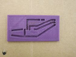
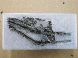
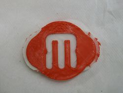
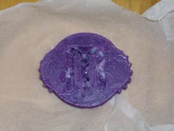
Below are pictures of two prints that used PVA as a support material, before and after dissolution. The print was done in two times as it had to be stopped because the PVA extruder got clogged. It was then restarted and finished, but the final appearence isn't satisfying.
HIPS
Because PVA is so difficult to extrude, we are also experimenting with HIPS (High Impact Polystyrene). Yet lot easier to extrude, this filament is dissolved by D-Limonene. This chemical can easily be found and is non-toxic, but it is obviously much more costly than using water. We will see that HIPS can also be dissolved by Turpentine.
Compared to PVA, HIPS is much easier to extrude and it doesn't tend to clog the extruder. A correct extrusion temperature on our printer seems to be 210-220°C on T0. Although the use of HIPS compared to PVA is much easier, it doesn't stick perfectly to the PLA or to itself. Therefore, a special attention should be paid in levelling the hot tips along the Z axis as HIPS could be dragged if a hot tip were too low. Besides, if the first layers of the print are made of HIPS, make sure they stick as much as possible on the bed.
Below are pictures of the same print that were performed with PVA, and it can immediately be noticed that the result is much more satisfying.
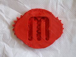
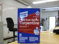
The HIPS needs now to be dissolved. We first tried to dissolve HIPS with turpentine as it is very easy to find this product for cheap. The part was submerged by turpentine and we let it sit overnight. If this chemical does dissolve HIPS, the result is not very satisfying. HIPS is softened and turned into a glue texture. Big chunks can easily be removed on the outside, but it is complicated to remove HIPS from the internal cavities like in between the teeth of the gears. Besides, you should consider wearing gloves in order not to have to wash your hands to remove this glue and the very strong smell of turpentine. Below is the result obtained after an overnight bath in turpentine for the gear box part. It can be seen that some glue still needs to be removed.
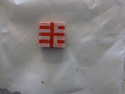
After these tests with turpentine, we were given some pure D-limonene from a chemistry lab. The Hilbert cube was submerged into the limonene for the night along with the gear box part for which some HIPS was still not dissolved as the turpentine didn't have a completely satisfying effect. After only an hour or two, the limonene which was translucent in the beginning, turned cloudy and the HIPS was already dissolving. After an overnight bath in limonene, the remaining HIPS on the gear box was fully dissolved and the Hilbert cube was washed from the remaining chunks of HIPS.
As a conclusion, limonene should be preferred to turpentine for several reasons. First, the turpentine doesn't dissolve HIPS correctly and it takes a longer time to achieve less good results. Then the smell of turpentine is really powerful and you should consider doing your experiments in a well-ventilated place. On the contrary, the limonene vapors aren't harmful and the smell is discrete and nice. Finally, limonene will dissolve most of the HIPS without much efforts with an overnight bath and the remaining chunks will easily come off with any appropriate tool.
Below are some pictures of the experiment with limonene.
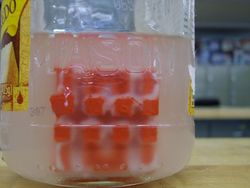 Hilbert cube dissolving after 2 hours in limonene.
Above is the gear box after dissolution of the HIPS into the limonene. Contrary to the turpentine, limonene dissolved the HIPS completely. However, the layers constituting the gears are delaminating. This is due to the design of the part. Indeed, while printing the gears, there are also layers of support that are being printed which shouldn't be. As a result the gears are not solid and when the HIPS is being dissolved some layers of PLA are separating. A solution to this issue could be using Slic3r to generate the support instead of using the original support material file. Below is a result of the print performed this way. The overhang threshold was set to 45°.
The result is not satysfying as support material was not generated between the top layer of the gears and the gear box, resulting in a non functional part. However, if the overhang threshold is set to 0 (for automatic detection) it was observed in Repetier that the support is achieved correctly. The print with this setting has still to be performed.
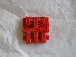
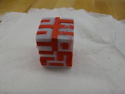
Above is the Hilbert cube after full dissolution of the HIPS. Note that the geometry of the print is different from the STL file. This is due to our printer which was still experimenting problems. The print stopped two times, and we had to restart it from where it stopped.
Below are the related ZIP archives:
| Item | Description | File Link |
|---|---|---|
| Hilbert Cube | Contains the two STL files and the AMF assembly | Media:Hilbert Cube.zip |
| Gear box | Contains the two STL files and the AMF assembly | Media:Gear box.zip |
Print Gallery
In this section we will upload pictures of interesting prints realized with our dual extruder. The related files can be found in ZIP folders in the ZIP section of this page.
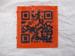
Below is a picture of a 3D printed QR code which is a link to this wiki page. The result needs to be improved, but it is working as it is with a QR reader on any smartphone.
Here is how we proceeded to print this part:
- Choose the URL you to want be encoded and use an URL shortener to simplify it: the simpler the URL, the simpler the print job will be.
- Generate a 2D QR code with any QR code generator.
- The next step will require a 130*130 pixels picture maximum, hence you need now to reduce the QR code picture you have just generated. We used Picresize. A picture of 100*100 will also work.
- With this picture you are now about to generate two 3D STL files, one for the positive patterns and one for the negative. We used this very useful website 3d Azurewebsites made by Michael Kappel. You just have to choose the height of your QR code and upload your picture. Do this a first time and save the STL file, then do it a second time ticking the box "Invert".
- With these two STL files, use Slic3r as you normally use it for dual printer jobs. As there are a lot of tiny features, we noticed that better results can be acquired by reducing the extrusion temperature by 5-10°C.
