StrongPrint
This page is a development stub. Please enhance this page by adding information, cad files, nice big images, and well structured data!
//identifies pages under construction. remove when the page is relatively stable.
Release status: Experimental
| Description | Metal 3D printer inspired from Metal Delta RepRap v1
|
| License | |
| Author | |
| Contributors | |
| Based-on | |
| Categories | |
| CAD Models | |
| External Link | (none)
|
Contents
Background
Inspired by the Metal Delta RepRap v1 to propose a very affordable metal 3d printer but it is based TIG (GTAW) process which has the potential to be more precise and it allows to use a cheap low power inverter MMA welding power source. The objective for this printer is to be below 1000€ cost & 2mm weld thickness.
- All documents required to build this printer are available on thingiverse
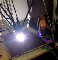
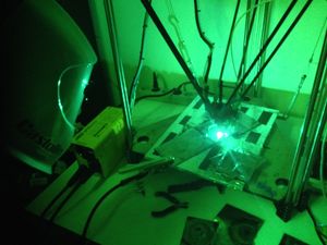
It has been developed in two month thanks to the support of the Artilect FabLab in toulouse. It is not yet operational but it is able to deposit metal on a steel plate.
Some videos are available online:
- Arc ignition test by the liftarc method: YouTube: StrongPrint - Arc initiation Test
<videoflash>HJQUvF1kOV0</videoflash>
- Metal deposition test with three layers: YouTube: StrongPrint - 3 layers Test
<videoflash>ro6W5TgIXXA</videoflash>
General Design
The printer is based on the Enlarged Rostock which was based on the Rostock from Johann
Document under construction, more details to come soon...
Bill Of Materials
Components On the machine at present: (Cost ~750€)
- Welding source: GysMi 160p 199€ (any inverter based MMA sufficiently powerful power source should do, I started with a 80A which was too low ) (150€ to 250€ for simple MMA sources)
- Round Shaft: 12mmx1000mm Z-12-1000A x 6 -> 90€ Obtained From HPC Europe
- Linear Bearings 12mm KB-12-WW x 6 -> 67€ Obtained from HPC Europe
- Belt 2m T2.5 x3 & Pulley 16 tooth x3 -> 75€ + 19€ Obtained from eMotion Tech
- Gen 7 V1.4.1 board x 1-> 145€ (the more recent & cheaper Ramps or ramps-FD + arduino due might be a good choice )
- Nema17 400 step/turn x3 -> 47€ Obtained from Selectronics (for the 3 axis)
- Nema17 200 step/turn x1 -> 16€ eMotion Tech  ( for the extruder ) lower steps is better for rapid retract
- Carbon rods -> diam 8 Kite frame from Decathlon
- Donut magnets x12 -> 12€ ref: R-15-06-06-N from Supermagnete
- Steel balls diam 12.7 x12 -> 4€ ref:K-13-N from Supermagnete
- USB-A Female plugs x4 -> 4€ from Electronique-Diffusion
- USB-B Female plugs x4 -> 4€ from Electronique-Diffusion
- USB printer Cable x4 -> 12€ from Electronique-Diffusion
- 9pin SubD conector Male & female -> 2€ from Electronique-Diffusion
- Bearings x5 -> From roller blades 5€
- Recuperated 10mm thick steel plate -> 30€ ()
- 12V 6mm solenoid valve x1 -> 4.20€ from Banggood
3D Printed parts ABS only due to the severe environment:
- Motor_End x3 -> http://www.thingiverse.com/thing:71687
- Idler_End V1.2 x3 -> http://www.thingiverse.com/thing:143186
- Bed x2 -> http://www.thingiverse.com/thing:74119
- MiniStruder x1 -> http://www.thingiverse.com/thing:310705
- Magnetic Carriage x3 -> http://www.thingiverse.com/thing:303637
- Ball Holder for Magnetic Bearing x12 -> http://www.thingiverse.com/thing:305411
- Magnetic Platform Tool -> http://www.thingiverse.com/thing:305118
- SR17 Torch Holder x1 -> http://www.thingiverse.com/thing:319442
- Nozzle Holder x1 -> http://www.thingiverse.com/thing:313475
- Springy Clip x6 -> http://www.thingiverse.com/thing:312016
- Tungsten level Cup x1 -> http://www.thingiverse.com/thing:326091
Conponent identified for the planned upgrades:
- Welding plate -> Thick copper or aluminium plate
- 10K Digital potentiometer -> AD5175 or similar to control welding power source
- Inductive Curent sensor -> to measure welding current
- Optocouplers -> to isolate electronics from the welder control to the printer control
- HF ignition system -> Coil, condenseurs, etc...
Head design
Platform
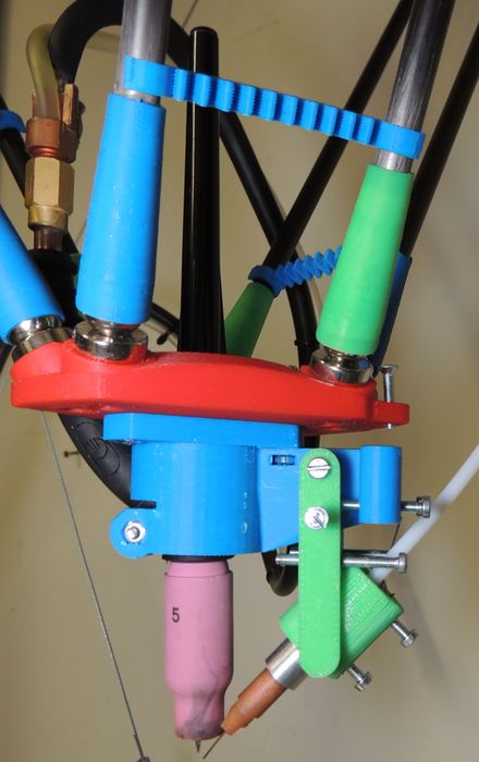
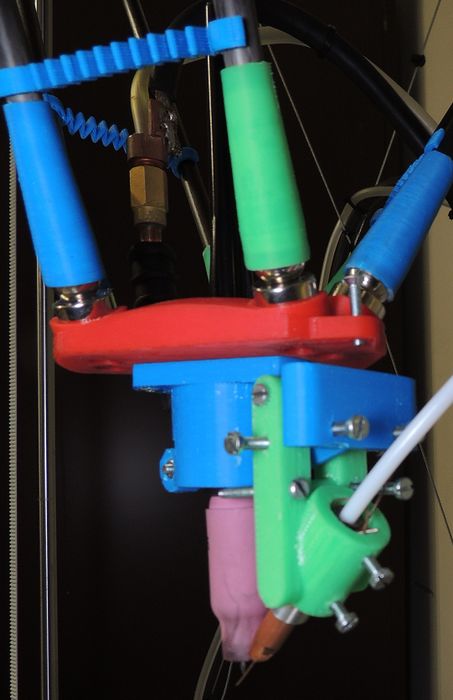
The platform (red part) is mounted on a magnetic bearings to the diagonal rods allowing different beneficial features:
- No play even with aging
- Rapid platform change therefore possibility to switch between a platform equipped with an hot-end for standard PLA/ABS & the metal one
- It gets disjointed instead of braking when hitting an object or performing an inappropriate movement.
Planned improvement: Integrate electrical circuit within the joints to check for the continuity of each magnetic joint & stop the printer in case of disjointment.
Torch Holder
The torch holder (blue part) is designed to tightly fit a SR17 torch tip & to hold the wire feed nozzle (green). this path has the following functions:
- Can hold the welding torch
- Ensure access to the torch cap to set the tungsten.
- Can hold the wire feed nozzle
- Allow precise control of the wire feed nozzle position
- Can be fitted to the platform
Welder Adaptation
For the moment a 80Amps basic inverter based stick welder (MMA) is used as power source. The following are important items for the choice of the welder:
- Being able to take control with an Arduino: it should be inverter based & relatively simple, on the GYSmy 80p that is used for the time being the power is set via a 10k potentiometer which could be replaced by a digital potentiometer controlled by the Arduino.
- Feature Standard 10/25 connectors to be able to fit a TIG torch
- More power 80A is a bit low.
To do:
- Install digital potentiometer to control welder power via arduino
- Install current & tension sense on the weld line
- Install HF start
Jobo, 200A
User Jobo is contemplating a MMA 200T1 MATECH IGBT Inverter welder ... need 200A, that I can get for 200 Euros. Contemplating attaching the welder head to a P3Steel, and then will attach an aluminium bed.
Wire feed system example
File:Millermatic.zip== Wire feed system, for a millermatic auto welder of lower ampage used by Joshua Pearce == Ebay Source: http://www.ebay.co.uk/itm/MillerMatic-A1D-4-wire-feeder-/142073790061?hash=item211441fe6d:g:RFEAAOSwPhdU-Jx1, 250$!
Toothed 6 Feet 2M MIG Spool Gun Wire Feed Aluminum Torch http://www.ebay.com/itm/Toothed-6-Feet-2M-MIG-Spool-Gun-Wire-Feed-Aluminum-Torch-/182318240341?, 50 bucks US
Electro Magnetic Shielding
The welding arc is a powerful source of electromagnetic interference, it is important to properly protect all cables from this as it might interfere with or even damage the electronics of the control board.
For the endstops Ethernet cable was used & connected to the control board via a 9 pin RS232 plug. parts that could not be replaced by ethernet cable wrer covered with aluminium tape. the endstop boards were not protected for the time being but it represents only a small wire length.
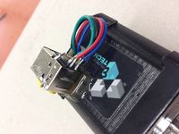
For the steper motors, there is an added dificulty that the connection wires should sustain a few Amps for which the ethernet cable felt thin. Printer USB cables seemed to have a more acceptable section.
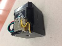
- A USB-b plug was installed on the motor side & fixed with epoxi as on the picture, the motor wires welded to the USB-B plug & a grounding wire between the plug ground & the motor casing. the welds were insulated with electrical tape & covered with aluminium tape.
- A USB-a plug on the control board side.
Software
An specific G-Code generator adapted to generate simple print test has been developed and is available on Github This was required specifically because pushing the wire slowly as required by the amount to deposit causes the wire to spend to much time in the very hot region close to the arc & melt before it's expected destination. Thefore each secment are cut in small subsection were the wire is alternatively pushed & retracted rapidly allowing the wire to melt in the weld pool as expected.
Assembly
Instructions
The Strong print Printer share the same Frame structure as the Enlarged Rostock
Assembly of the machine is as simple as a large IKEA furniture:
Assembly of the frame:
1 - Build the three columns:
- Assemble the Iddler End: http://www.thingiverse.com/thing:143186 with the beraing & the bolts
- Assemble the Motor End: http://www.thingiverse.com/thing:71687 with the stepper motor & the pulley
- Assemble the Magnetic Carriage: http://www.thingiverse.com/thing:303637 with two R-15-06-06-N magnets, insert two KB-12-WW Linear Bearings in the housings & tighten the M3 bolts
- Assemble the Column:
   - Fit the two Z-12-1000A smooth rods on the Motor End
   - Insert the Magnetic Carriage with the magnets facing towards the motor side of the motorend (fix them with Epoxi not hot glue). The linear bearings shood fit smoothly on the roods with no play.
   - Fit the Iddler End with the bearing on the same side as the puley on the Motor End.
   - Ensure everithing is straight & square with no twist & tighten the M3 bolts of the Iddler end & the motor end
   - Fit the T2.5 belt to the tension nut from the carriage, Attach the tehsion nut to the carriage with two long M3 bolts & nuts. pass the belt arount the puley & the bearing and fix the end to the adapted bit on the carriage sith a slight tension, which can then be ajusted with the long M3 nuts.
- This is it you now have three columns fully equiped.
2 - Assembly of the frame structure with the columns
- Bolt the reinforcment bar to the printer Bed & Top: http://www.thingiverse.com/thing:74119
- Screw one by one the MotorEnd of the Three columns to the printer Bed
- Screw the printer top on top of the three columns
- Fit the tension cable to the reinforcment bars while crossing them (the tension cable are optional it rigidifies the structure which is only needed for fast printing with plastic)
- Apply moderate tension to the tension cable ensuring no twist or deformation is created in the frame .
- The structure is now fully assembled
Safety
The inherent risks & safety precautions of wellding applies see Welding Health & Safety
- Fire hasard - Remove all flamable material around the the printer & have a fire extinguisher ready.
- UV & eye protection - wear adequate welding helmet for all people watching the print & long sleve coton shirt.
- Fumes are unhealthy
