Stripboard JDM PIC Programmer
Note: This is a preliminary design and has not yet been tested
Contents
Disclaimer
Connecting devices to your serial port is a slightly risky business. If you mess up really badly, it is possible (though unlikely) that you could damage your serial port. The risk is entirely yours and we take no responsibility for any damage you may cause by incorrectly building or using the programmer.
Introduction
This is based on the original JDM programmer design. The original design requires either a PCB or fiddly fabrication on plain perforated board. The design outlined here uses the same stripboard methods as suggested for other modules and is simpler to build.
This programmer is only required for bootstrapping a machine (see RepStrap), as the complete machine will include it's own PIC Programmer.
Requirements
Tools and consumables
- A soldering iron and accessories (see the Electronics Fabrication Guide).
- Solder
- Electric drill or at least a suitable drill bit
- Some wire for jumpers/links
- Wire strippers
- Small pliers or tweezers
Components
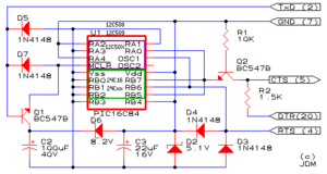
- R1: 10kΩ Resistor
- R2: 1.5kΩ Resistor
- C2: 100μF electrolytic capacitor (25V or more)
- C3: 22μF 16V or 47μF 6.3V tantalum capacitor
- D2: 5.1V zener diode (0.5W or more)
- D3: 1N4148
- D4: 1N4148
- D5: 1N4148
- D6: 8.2V zener diode (0.5W or more)
- D7: 1N4148
- Q1: BC547B NPN transistor
- Q2: BC547B NPN transistor
- An 18 pin IC socket
PC Hardware
This design is only suitable for use with serial ports that appear in the I/O space of the PC. In simple terms, this means it is not suitable for USB-to-serial converters. We're working on this.
Schematic
Preparing the board
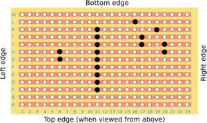
The strips on the back of the board need to be "separated" at certain points. The easiest way to do this is to use a small electric drill with a drill bit around 3-4mm in diameter. Don't drill all the way, just far enough to cut the copper tracks - you may find a 3.5mm drill in a hand-held chuck is easier to control. See the Electronics Fabrication Guide for more details.
This image shows the rear of the stripboard so you can see the points that were separated.
The points marked in black are where you should separate the tracks.
Note: This is the minimum size. It is recommended that you leave sufficient additional space on all sides to allow for easy mounting. Around 20mm will be ample.
Important: There are some voltages that can and will damage components if you aren't careful. Double and triple check that:
- You have completely separated the necessary tracks. Use a multimeter or continuity checker if you have one.
- You have not connected any two adjacent tracks with shards of copper. It is a good idea to scrape down the channels to ensure there are no fragments. Again, check this with a multimeter or continuity checker.
Making the board
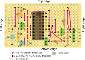
Solder the components into the board as pictured below. See the Electronics Fabrication Guide if you're new to soldering or component placement.
Pay particular attention to transistor and diode orientation.
For a BC547B, when looking at it from the flat side, then from left to right the pins are in the order emitter (E), base (B) and collector (C).
Board connections
The following are numbered top down as seen on the diagram of the component side of the board.
- J1 - Serial connector
- TxD
- GND
- CTS
- DTR
- RTS
- J2 - Mode selection
- Common
- For old PICs
- For new PICs including 16F628 (for RepRap projects)
If you're planning of programming a variety of PICs, you should connect J2 to a switch so you can easily switch configurations. If you're only planning on programming PICs for the RepRap project, you can just hardwire pin 1 to pin 3 with a wire link (and leave pin 2 disconnected).
Usually you will be connecting a cable from the programmer to a 9-pin serial connector for plugging into a PC. Use a female 9-pin connector. Wire J1 as follows
- TxD to pin 3 (on the 9 pin connector).
- GND to pin 5
- CTS to pin 8
- DTR to pin 4
- RTS to pin 7
PIC Programming Software
If you're using Windows, probably the best piece of software to use is ic-prog. See ICProgHints for more details on settting it up. If you're using Linux, Pikdev works very quickly and reliably.
Testing
Before using the programmer, you should check it is built correctly.
First (with the programmer unplugged), double check all connections with a multimeter (usually set to low resistance range) or continuity checker. Check everything that should be connected is, and everything that shouldn't be connected isn't.
Double check the diodes are all the right way around. The end with the band is the negative end, and it also corresponds with the bar side of the diode in the schematic symbols.
Check the diodes again.
- Using a multimeter, measure the voltage on the IC socket between pin 5 (-) and pin 14 (+). It should be just below 5V.
- When you tick Enable Data Out, the Data In checkbox should also become ticked (and vice versa). You cannot directly tick the Data In checkbox.
- Measure the voltage between pin 5 (-) and pin 13 (+). It should read around -2V to -2.5V. When you tick the Enable Data Out checkbox, it should swing to 4.5V to 5V.
- Measure the voltage between pin 5 (-) and pin 12 (+). Tick the Enable Clock box and it should go to +5V (or a little more). Untick it and it should return to 0V (actually about -0.5V to -0.8V).
- Measure the voltage between pin 5 (-) and pin 4 (+). Tick the Enable MCLR box and it should go to +12V. Untick it and it should return to 0V (actually about -0.5V).
Variations
The 1N4148 diodes may be replaced with 1N4448 or other equivalent diodes if more readily available.
D5 and D7 may be replaced by a BC557B. Emitter to MCLR and Collector to Vss.
Troubleshooting
See Also
- RepStrap
-- Main.SimonMcAuliffe - 11 Mar 2006


