SinapTec
|
English • العربية • български • català • čeština • Deutsch • Ελληνικά • español • فارسی • français • hrvatski • magyar • italiano • română • 日本語 • 한국어 • lietuvių • Nederlands • norsk • polski • português • русский • Türkçe • українська • 中文(中国大陆) • 中文(台灣) • עברית • azərbaycanca • |
SinapTec AT328.02 is a 3D FDM printer controller board of very low cost, its operation is based on an Arduino Nano or CHIP running a version of Teacup Firmware. The board layout is designed so that it can be manufactured by any hobbyist, it is a simple face plate with 2 layers and through-hole components,(1 layer is easy soldered with scap wires to an etched PCB).
Release status: Working

| Description | SinapTec AT328.02
3d printer controller board based on Arduino Nano.
|
| License | |
| Author | |
| Contributors | |
| Based-on | |
| Categories | |
| CAD Models | |
| External Link |
Contents
Summary
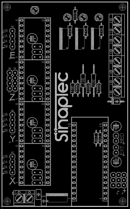
- 1 Arduino Nano socket.
- 4 Pololu sockets (X,Y,Z and E)
- 3 Line in for X_MIN, Y_MIN and Z_MIN endstops.
- 2 Line in for Hotend and heated bed sensors.
- 3 Mosfets outputs for Heater, Fan and Bed (this last with independent power supply).
Image Gallery


Extra Files
File:TeaCup - CoreXY.zip (outdated, use Teacup Firmware#Simple Installation)
File:PCB.brd PCB.brd (EagleCAD software design)
File:PCB (Transferencia de Toner).pdf PCB diagram for transfer toner
File:SinapTec.gcode.zip Gcode for PCB CNC Milling and Drilling
[http://reprap.org/mediawiki/images/f/f7/Board.pdf Board schema in color pdf
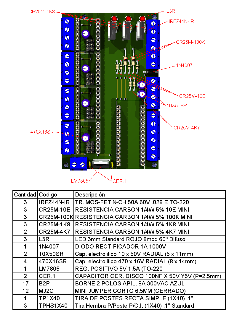
Bill of Materials (BOM), English
| Number | Item | Description |
|---|---|---|
| 3 | MOSFET | N-Channel MOSFET IRFZ44N-IR 50A 60V TO-220 |
| 3 | 1/4W Resistor, Carbon | CARBON RESISTOR 1/4W 5% 10ohm |
| 3 | 1/4W Resistor, Carbon | CARBON RESISTOR 1/4W 5% 100kohm |
| 4 | 1/4W Resistor, Carbon | CARBON RESISTOR 1/4W 5% 1.8kohm for LEDs |
| 2 | 1/4W Resistor, Carbon | CARBON RESISTOR 1/4W 5% 4.7kohm |
| 3 | LED | LED 3MM STANDARD RED 8MCD 60° |
| 1 | LED | LED 3MM STANDARD GREEN 8MCD 60 |
| 1 | DIODE | 1N4007 DIODE RECTIFIER 1A 1000V |
| 2 | CAPACITOR | ELECTROLYTIC CAPACITOR 10uF 50V RADIAL (5 X 11 MM) |
| 4 | CAPACITOR | ELECTROLYTIC CAPACITOR 470uF 16V RADIAL (8 X 14MM) |
| 2 | CAPACITOR | CERAMIC CAPACITOR 100nF 50V |
| 1 | VOLTAGE REGULATOR | LM7805 5V 1.5A T0-220 |
| 5 | SCREW TERMINAL | Screw Terminal 2P (2 hole) 5mm 8A 300VAC |
| 12 | JUMPERS | MINI JUMPER 6.5MM |
| 1 | HEADER PIN | Pin Header 1x40 Male 2.54 mm |
| 3 | HEADER PIN | Pin Header 1x40 Female 2.54 mm |
Board Connection Diagram Pin Out

Warnings
Reversing +/- or otherwise incorrectly connecting power can destroy your electronics and cause fire hazard.
Incorrectly inserting stepper drivers will destroy your electronics and cause a fire risk. Always make sure power and USB is disconnected when removing or adjusting stepper drivers. Always make sure to insert drivers in correct orientation and in the socket correctly.
The endstop pins are Signal - GND - VCC, instead of the VCC - Sig - GND like the rest of RepRaps boards. Make sure to wire them correctly. This is done to allow squeezing fatter traces on the printable board.
DON'T secure SinapTec AT328.02 with conductive screws through both mounting holes. The screw may cut into the positive trace creating a HIGH current short.
Best Practices
A best practice is a technique or methodology that, through experience and research, has proven to reliably lead to a desired result.
Use a more rugged choice of MOSFET. Use a suitable high power fuse to the hot-end and the heated bed. A cooling fan is recommended
Development
Ruggedisation
Make the board more resistant to extreme situations: Electrics Climate Salt water Misuse/human error/poor handling
Usage environment: Offshore, on a ship or a vessel
- Active cooling over the electronics with a 80mm cooler is recommended.
| 12v 80mm Cooler |
|---|

- To avoid overheating or the use of heatsink is recommended to change the hotbed's mosfet for one of better quality, such as a IRLB3034, IRLB8743, or similar.
- It higly recommended to place a fuse on power input of 5A and 10A (or 11A to match RAMPS) for the bed.
| ATO / ATC Fuse | Cartridge Fuse |
|---|---|


Drivers Characteristics and Configuration
The following table compares the DRV8825 vs A4988 driver that can be used on this board.

| A4988 | DRV8825 | |
|---|---|---|
| Availability | very widely available | widely available |
| Approx. price | $6.80 / 5 pieces | $10 / 5 pieces |
| Max. theoretical current | 2A | 2.5A |
| Max. microsteps | 16 | 32 |
| PCB color | Green / Red | Purple |
| Stepper current adjust. trimpot | Yes, near Dir pin | Yes, near En pin |
| Typical Rs value | 0.05 Ohm or 0.1 Ohm or 0.2 Ohm |
0.1 Ohm |
| Vref formula (*) | I_TripMax= Vref/(8*Rs) | I_TripMax= Vref/(5*Rs) |
| Thermal Overload Protection (**) | Yes | Yes |
| PCB layers | 2 | 4 |
| Small heatsink included (***) | Almost always | Sometimes not |
| Active cooling required? | Recommended | Recommended |
| IC packaging | 5x5mm 28-lead QFN | 9.7x6.4mm 28HTSSOP |
Note that some important technical characteristics from the respective datasheets of the ICs are not directly comparable. For example, the DRV8825 is fully specified in terms of thermal characteristics, the A4988 is not. Another important characteristic that unfortunately is not directly comparable is RDSon, which is specified at different current levels in the respective IC datasheets.
(*) Adjusting the stepper driver current
See these instructions: Pololu_stepper_driver_board#Tuning_motor_current.
(**) Temperature Overload Protection
It is very important to keep the stepper driver ICs below a certain temperature during printing, since both ICs feature thermal overload protection that when triggered (typically when the die reaches a temperature of around 150~160 C), shuts down the output stages i.e. halts all commands to the affected stepper and in doing so, ruins the part being printed.
(***) Heatsinks
It is not yet determined how much of a real impact the small aluminum heatsinks have on cooling the ICs, as both stepper driver ICs depend much more on proper PCB layout and solder pad contact (as well as proper airflow, remember!) for heat dissipation, rather than on dissipation through the top of the IC package. This is because both stepper driver ICs have an exposed metal pad under the chip that contacts the PCB and this is the "path of least resistance" for heat dissipation. The secondary path for heat dissipation is through the package leads and in this aspect the DRV8825 provides for possibly slightly better power dissipation compared to the leadless A4988. It is my understanding that dissipation through the top of the ICs is almost irrelevant here.
Build Instructions
Teacup firmware: config.SinapTec-vAT328-02.h (outdated, use Teacup Firmware#Simple Installation)
Jumpers Configuration
| A4988 | DRV8825 | |||||||
|---|---|---|---|---|---|---|---|---|
| Jumper 1 | Jumper 2 | Jumper 3 | Microstep
Resolution |
Jumper 1 | Jumper 2 | Jumper 3 | Microstep
Resolution | |
| No | No | No | Full Step | No | No | No | Full Step | |
| Yes | No | No | Half Step | Yes | No | No | Half Step | |
| No | Yes | No | 1/4 Step | No | Yes | No | 1/4 Step | |
| Yes | Yes | No | 1/8 Step | Yes | Yes | No | 1/8 Step | |
| Yes | Yes | Yes | 1/16 Step | No | No | Yes | 1/16 Step | |
| --- | --- | --- | --- | Yes | No | Yes | 1/32 Step | |
| --- | --- | --- | --- | No | Yes | Yes | 1/32 Step | |
| --- | --- | --- | --- | Yes | Yes | Yes | 1/32 Step | |
Notes:
*Jumpers need to be installed under each stepper driver.
*1/16 Microstep Resolution is the default thats being used.
Datasheets
MicroSD card interface
Dejaworks show that pin D4 is the only pin connected direct to the MicroSD card, using SPI. Adafruit MicroSD reference is also relevant research. Pin D4 of the Arduino Nano is connected to the PCB.