SeeMeCNC-H1 Build Notes
These build notes are user-submitted tips and advice you may find useful during your own build.
You are encouraged to add your own notes to this page, as well as to modify any tips you see with your own improvements or corrections.
Please discuss any new modifications or risky changes you see here on the message board before attempting. Just because it worked for someone else doesn't mean its a good idea for you.
Contents
- 1 Tools
- 2 Pre Drilling
- 3 Bearing Fitting
- 4 Electronics Bench Test
- 5 71578 - Double Bearing Sub Assemblies (2)
- 6 71579 - Triple Bearing Sub Assemblies (8, but only 2 fully assembled in this step)
- 7 71577 - Combo Bearing Sub Assembly for X Carriage(2)
- 8 71576 - Z Axis Bearing / X Axis Gantry Sub Assembly (2)
- 9 71580 - Front Base Sub Assembly (1)
- 10 71581 - Front Base Sub Assembly (1)
- 11 71582 - Z Axis Base Sub Assembly (2 Bearing Plates that mount into 1 sub-frame)
- 12 71590 Steve's Extruder
- 13 71523 Offset Support Rod (Rod Bending)
- 14 71583 Frame Assembly
- 15 71584 Y and Z Axis Installation
- 16 71574 H1 Extruder Barrel (Hot End)
- 17 Life Test
- 18 Hot Test
- 19 Burn In
- 20 Calibration
- 21 Printing
- 22 Mods: Opto Mod/Skewfix
- 23 Mods: Stepmod
- 24 Further reading
Tools
The build will require:
A philips head screwdriver (preferably electric)
1/4", 3/8", and 7/16" wrenches or adjustable wrench. It is nice if the 1/4" wrench has a closed end to hold the small locknuts captive.
3/32", 7/64", 5/32", and 3/16" allen wrenches. It would be best if the 3/32" were a screwdriver tip due to the large number of Cap Head screws for the 90 degree bar clamps. the 7/64" is used for the extruder tensioning screws, and is a bit of a nonstandard size. Go buy one, or you'll just bugger up the most often adjusted piece of your machine.
Tape Measure
5/32", 1/8", and 1/4" Drill Bits.
Pre Drilling
The holes in the plastic parts are a bit tight at times, especially when threaded components must pass through. For the case of the 60 degree bar clamps at the centers of the threaded rods, adjustment can be very difficult due to the tight fit. This situation can be eased by drilling the holes out with an appropriately sized drill bit.
71514/71516 - Triple Bearing Support/Cover. ONLY TWO of each of these should have their 4 mounting holes drilled to 5/32". This is an official mod and is listed on pg 71576. This is needed to fit the #8 sheet metal screws through.
The rest of these are unoffical mods.
71508 - Bar Clamp 90 Degree. Drill all 4 corner holes on each with 1/8" bit, to prevent binding when mounting with the 1-1/4" Socket Head Cap Screws (SCHS)
71501 - Bar Clamp 60 Degree. Drill the 2 outer (large) holes to 1/4" to prevent binding on the threaded rod.
Bearing Fitting
This section is for those who are replacing the delrin bearings with R2ZZ's. Electronrancher found that his bearings were too tight on the shaft (some impossible to fit), and used a Dremel tool to spin the shaft and sand them down a bit.
Place the clean end of the shaft about 1/8" into the Dremel and power up to a moderate speed (15k RPM). Use a flat sanding device, like an emery board or sandpaper wrapped around something flat to sand down the flared end so it's flat, as well as to slightly sand the shaft down. After about 10 seconds with lightly held sandpaper, power down, wipe the shaft and check the fit. After a few, you should be able to judge the timing automatically.
Go ahead and fit all the bearings and washers on the shafts first, so they are ready for the next steps. In order to make sure your bearings are centered on the shaft, a spacer can be made by stacking up two of the delrin bearings and taping them together. This luckily ends up being exactly half of the empty space when an R2ZZ and a washer are also put on the shaft, so it makes centering a one-push deal.
Electronics Bench Test
The 450 watt power supply that either comes with the kit or one that you supplied is more than ample to power everything that you need. Here's a tip to keep all of those power wires clutter free. Once you determine the ground, +5 and +12 wires that you need, as well as the green wire to trigger on the power supply, open up the power supply case. You will see that all of the red wires are connected to one area of the circuit board. This goes for the black wires and yellow wires. You can either cut off the unneeded wires flush with the circuit board or actually unsolder them. You can also take this time while the case is apart and mount a SPST switch that will connect the green wire to a black wire.
71578 - Double Bearing Sub Assemblies (2)
Build these first - it's the simplest component and a good way to get your build skills limbered up. For the captive nut/screw combo (the 4/5 in the pdf), you may want to hold the nut in a wrench and get the screw a few threads through the nylon locknut to avoid it flipping around if you tried to screw it in an uncapped assembly.
The actual assembly is a piece of cake - drop in two bearing/shaft combos and screw the lid on. You may want to put all the screws through and hold with your fingers while you thread on the nuts. Then, tighten each in turn.
Look at that, you're building a reprap!! Put a smooth rod through one and feel the sweet double bearing action - that's going to be your table walking back and forth!
71579 - Triple Bearing Sub Assemblies (8, but only 2 fully assembled in this step)
We'll stuff all the triple bearing sub assemblies for future use, but only two get their lids put on in this step. If the 71514 support is oriented like a T as shown in the PDF, it gets one captive nut/screw combo (a 4/6) in the lower left, and two of the six assemblies get one captive nut (the 6's, flat side out) in each of the upper right and upper left slots. Those two (with the captive nuts) will get their covers put on now. The six without captive nuts will be used for other steps. If you have already drilled four of them to 5/32, make sure those are saved and not used for this step.
When dropping in the three bearing/shaft rods, the horizontal one goes in first, then upper right, then upper left on top of that.
71577 - Combo Bearing Sub Assembly for X Carriage(2)
You should have two shells left for both the double and triple bearing supports. They will be stuffed here and attached to the 71519 combo bearing support for the X-Stage. Stuff the bearings and the captive nut/screw tensioner normally, but note that only the upper left captive nut slot in the triple is stuffed. Add the cover.
71576 - Z Axis Bearing / X Axis Gantry Sub Assembly (2)
Here you will use the four triple bearing blocks that were drilled to 5/32". They are screwed to the X-Axis motor mounts with the large (#4) sheet metal screws. It's best to attach the 71508 90 Degree Bar Clamps before the bearings because the upper bearing would block the rotation of an Allen wrench, if that's what you intend to use for the 30617 5-40 Socket Head Cap Screws. If you're using a hex screwdriver, then either order is OK.
71580 - Front Base Sub Assembly (1)
You may consider marking the centers of all rods to assist in alignment during the build. This is the first time you'll need it. soon...
71581 - Front Base Sub Assembly (1)
soon...
71582 - Z Axis Base Sub Assembly (2 Bearing Plates that mount into 1 sub-frame)
Press fit the R4ZZ bearings and install their holders (called 6/7/5). Pay attention to which side is up, and remember that the bar clamps go on the same side as the HEAD of the R4ZZ bearing holder. soon... Alignment/squaring!
71590 Steve's Extruder
Now is a good time to change pace and build the extruder. Seems like a lot of parts, breaking it down into a few simple sub-assemblies really simplifies things.
The bearings fit countersunk in the white gears, and can misalign the gears and cause binding if they are not fitted deeply enough. Flush does not seem to be good enough. Press the outer race when fitting, lest you risk damaging the bearing. When fully seated, a #8 washer can sit on top and itself be almost flush with the surface of the gear. It's deep. soon...
71523 Offset Support Rod (Rod Bending)
YoYo's method.
71583 Frame Assembly
soon...
71584 Y and Z Axis Installation
soon...
71574 H1 Extruder Barrel (Hot End)
- TIP*
Do not solder the power sires to the heating resistors. The temperature of the hot end is higher than the melting point of solder and your wires WILL come off. Instead, use crimp lugs to connect the resistors in parallel and to connect the power wires to the resistors. You can buy little crimp sleeves that are designed for this purpose, but it is simpler to grab a few of the crimp-on wiring terminals that you probably own already, cut off the "ring" or "spade" section, and just use the barrel for connection to the resistors.
Life Test
Once you are sure of your electrical connections, plug your LPT and power up the 3-axis board. Leave the hot end and extruder unpowered for the moment. Check function and proper direction of all motors
Hot Test
soon...
Burn In
You will find that the machine changes a bit over the first few prints. Belts stretch, the hot end may need re-tightened, idlers smooth out a bit. Consider your first few prints a burn-in period, like the first thousand miles on a car.
(need John to put his G-Code burn in routine here)
Calibration
Hint: When calibrating the 3 axis, turn each axis acceleration down. For the X and Y axis, change it from 900 to 9. This will allow you to get more repeatable results. For the Z axis, change it from 12 to 6. Once calibration is complete and all of your results are repeatable, restore the original acceleration values.
Printing
The table that is included with the printer was never intended in the first generation H-1 to be printed directly to. It is not 100% flat nor true to the Z axis. Users are using everything from a pane of glass, ceramic tile, and cheap cutting boards mounted on top of the included table to print on.
A good (and readily available) option is plexiglass. It can be taped or binder clipped to the stock table, with some paper shims for bed levelling, and gives good adhesion without painter's tape. It's also cheap and will give if you accidentally bury the hot end in the table due to Mach3's curious attribute of munging all the zero-values upon gcode readin. :)
Mods: Opto Mod/Skewfix
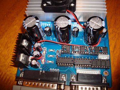
3 axis stepper driver board modifications: It has been found that there is a significant delay through the optocouplers on the TB6560 board that will effect printing enough that your object might become skewed. The solution here is to bypass the step and direction couplers responsible for each of the 3 axis with a jumper wire. Now typically you would never want to bypass/eliminate the functionality of an optocoupler but it was found that both side of the optocoupler share a common ground, almost defeating the use of optocouplers to begin with.
To perform this mod, take a piece of wire, similar to something like a resistor lead, remove the optocoupler, and connect pins 2 and 4 together.
Click the image for a full size version
Also, this document, File:4-axis Board fixes from CNCZone.pdf shows more modifications and circuit diagrams on the 4 axis version of the stepper driver board that is used in the H-1 that can be applied to the 3 axis version that is used.
Mods: Stepmod
The H1 ships with a stepper-based extruder, which is known to offer accuracy advantages over dc controlled extruders. To take full advantage of these benefits, the extrusion control should be calculated by your slicing software and embedded in the gcode, so movement and extrusion are synchronized throughout the build.
This mod consists of two parts: For those users with rev1.0 electronics (ramsey stepper), the ramsey board can be modified to accept step/dir signalling from Mach. For users with Easydriver or other aftermarket stepper boards, this first part is not necessary - those boards already run on step/dir control. For either set of hardware, the second part of the mod is to reconfigure the slicing tool and Mach3 to interpret and output the proper step/dir signalling to the extruder.
Part 1 - Ramsey Step/Dir Mod
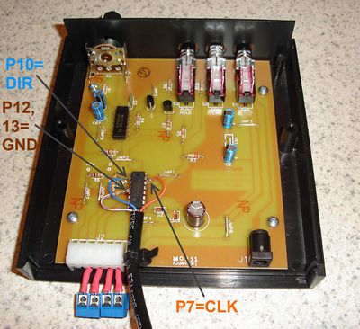
The MC3479 stepper IC on the ramsey board already uses step/dir signalling, it's just a matter of patching our own logic signals in at the right points. Pin 7 of the MC3479 is the step (CLK) input, and pin 10 is the direction input. As built, the ramsey board uses a couple of logic gates to generate an adjustable frequency used for stepping. By cutting jumper J2, you can disconnect this on-board clock from the '3479. No cuts are needed for the direction input, although it is required that the CW/CCW pushbutton be in the OUT position so it does not ground our direction signal. The ON and RUN pushbuttons should be in the IN position so the board is powered up and enabled. The relay used to switch the +5V on and off is no longer required, so you can wire +5V and GND directly to the ramsey board from the PSU.
We will obtain our step/dir signals from LPT pin 16/17, identical to the rev1.1 wiring diagram. These pins are available on a 4-pin expansion port located next to the optoisolators. The board has 1N4148 diodes in series with the pins, which can be shorted out to obtain the full LPT voltage at the expansion port. Although GND is shown as a connection on this board, it may not be necessary as the GND is shared between the +5V supply of the ramsey board and the +12V supply of the 3-axis board. However, it's safer to connect GND here as well in the event that one of the two power supplies becomes disconnected.
The connections to the MC3479 IC on the ramsey board are shown below. Alternatives to soldering directly to the chip are the inside lead of jumper J2 and the inside lead of R10. Inside being the closest side to the '3479. Refer to the schematic for finding alternate solder points.
A photo showing the solder points when directly on the IC.
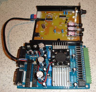
A photo showing the ramsey board connected to the 3-axis board.
Part 2 - Step/Dir Setup
At this point, you have the choice to run the extruder at a fixed speed, adjustable speed, or synchronized step. Synchronized step offers the most flexibility, although all three are suitable options and each will be described here.
Part 2A - Fixed Speed Spindle
Fixed speed with software on/off is the setup most closely related to the stock ramsey operation, with the advantage of much shorter on/off delays as a relay does not need to be switched. By setting up p16/p17 as a PWM controlled spindle in Mach3, a fixed speed extruder can be obtained. M03/M05 motor on/off controls will be properly interpreted in the gcode, and some software control can be obtained while keeping the setup simple.
<needs screenshot>
Part 2B - Adjustable Speed Spindle
By setting up p16/17 as a step/dir spindle, a software adjustable extruder with full on/off control can be obtained. This setup responds to M03/M05 on/off commands as well as Sxxx spindle speed commands.
<needs screenshot and setup details>
Part 2C - Synchronized Stepper Axis
By setting up the extruder stepper on p16/p17 to be a 4th axis (the A axis, for example), detailed control of the extrusion can be obtained. Using slic3r or the dimension plugin for Skeinforge, the actual length of cold plastic that should be extruded for each move is added to all G1 lines in the gcode. This should give more consistent extrusion as each step of X and Y are matched to the proper proportion of extruded plastic, giving a more uniform build in the case of arc slowdowns and other movements where speed varies.
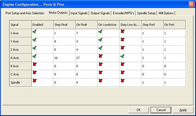
Port Settings are as follows
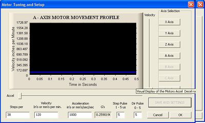
Motor Tuning is as follows - 38 steps per calculated using INPUT length of cold filament.
Software Setup
Skeinforge - no luck getting dimension plugin to work
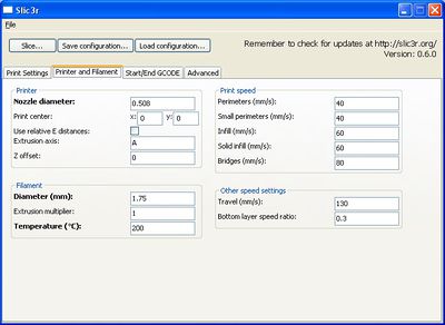
Slic3r - Change Extrusion axis to A, center to 0,0, and set nozzle and filament diameter
And you end up getting gcode like
G92 A0 ; reset extrusion distance
M82 ; use absolute distances for extrusion
G1 Z0.500 F7800.000
G1 X-14.070 Y-13.890
G1 F3600.000 A2.00000
G1 X-13.890 Y-14.070 F1080.000 A2.02235
G1 X-13.510 Y-14.410 A2.06712
G1 X-12.890 Y-14.850 A2.13387
G1 X-12.670 Y-14.980 A2.15630
G1 X-12.210 Y-15.210 A2.20146
Where the A axis is defining the number of mm of cold filament to be extruded during each move. Natch!
SFACT - Experimental so far. Latest version seems to generate good gcode, but for some reason still under investigation it makes the machine sound like it's having a seizure! This is using feed settings MUCH slower than slic3r, and slic3r's code whistled smoothly through at an astounding rate. Not giving up, though, as CLIP seems to be the key to blobless printing, and slic3r can't clip.
Further reading
- The incomplete reprap beginner's guide is a similar build guide.
- PrusaBuildNotesBraino is a similar build guide.
- Alternative Build Documentation attempts to be a "generic" build guide that lists the known options at each step.
