Scratchbuilt Piezo Printhead
Contents
This is a description of a simple DIY Piezo print head.
or to be more precise early attempts.
This page is a development stub. Please enhance this page by adding information, cad files, nice big images, and well structured data!
Release status: unknown
| Description | Piezo printhead
|
| License | unknown
|
| Author | |
| Contributors | |
| Based-on | |
| Categories | |
| CAD Models | |
| External Link |
See also Reprappable-inkjet.
Reason for doing this
Powder bed 3D printers mainly use bubblejet print heads, whilst a great deal of effort has gone into binders, powders,and the electronics to drive these print heads by the open hardware community they tend to be expensive and very intolerant of the fluids they can handle, this inevitably excludes many materials for binders, if the binder is strong enough the resulting part will have strength regardless of the powder used, A commercial print head has the obvious advantage of high speed and high definition, but a single nozzle head could act much like the reprap and use the same Gcode with some modifications perhaps,an arduino to control frequency, ramping etc, the possibility of wax parts is also feasible, waxes come in various types from children's crayons to specialized hard waxes,another possibility may be to jet a suitable solvent onto a powder polymer thereby fusing the powder.
Bimorphs
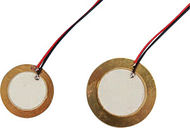
The last time I looked at piezo materials they were to expensive for the tinkerer to play with, after some searching,bimorphs, or buzzers seemed like the only affordable source of piezo actuators, whilst they have a low frequency compared to normal ultrasonics at the audible range of around 2Kh to 4Kh, this should be ample for pumping or jetting or spraying fluids, cigarette lighter spark units were extracted as a possible source but bimorphs were chosen as a starting point.
Some info on piezo electric
- Wikipedia: piezoelectricity
- Wikipedia: piezoelectric sensor
- "How Inkjet Printers Work"[1]
- InkJet
Here are instruction to build one if you have a Reprap, Reprapable version Reprappable-inkjet
First attempt
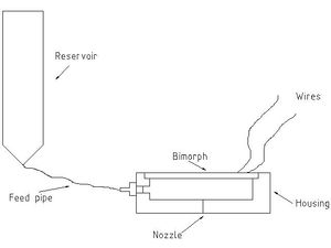
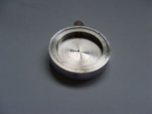
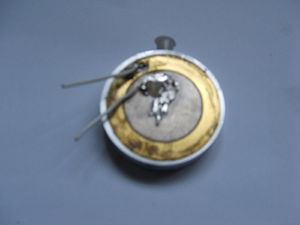
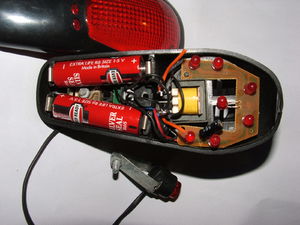
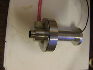
A pocket was machined out of some 40mm dia alluminium to accept the bimorph, also to act as a reservoir for the fluid, a hole on the circumference for fluid feed and a small hole in the centre of the alluminium to act as a nozzle, the smallest drill to hand was approx .5mm, the hole was swagged or closed with a ball bearing to reduce the size. The bimorph was glued in with the wired side facing out, a bicycle buzzer stripped down for the drive circuit was attached and water inserted, first results were disappointing with no sign of fluid emitting,the water was changed to white spirit but still no response, I realized that the fluid may be simply oscillating within the chamber, an adapter to allow a syringe was added to create more weight of fluid to the input side, this had the desired effect and the white spirit emitted from the small hole, a process of more swagging then trial resulted in a good spray, the cycle buzzer had selectable tones and gave different spray characteristics with different tones, white spirit was removed and Vodka added, this also worked well and was less unpleasant to work with (Hic).
Drive electronics
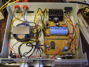
The drive electronics are very simple, a pulse generator feeding into a miniature step up transformer then to the bimorph, the pulse generator in the cycle buzzer was a surface mount device covered with potting fluid, this gave the different sound effects, but for better trials it was decided, due to the initial success, to build a drive unit to give variable frequency and amplitude to see the effect of these on the spray output
The drive used for trials, the transformer is not a high frequency type, but seems to work OK, bimorphs seem to work at around 100 volts, this drive goes up to 150 volts.
Initial results...
Video of printhead working here, (I know its rubbish): <videoflash type="vimeo">13973877|640|480</videoflash>
The bimorph was glued into place with superglue, although the bimorph was in poor condition it was still usable, and wash fluid (water with surfactant) added, a jet of fluid emitted when power was applied although difficult to see, black food colouring was added to improve visibility, the 3 main factors seem to be, nozzle diameter, frequency, amplitude,
Nozzle diameter... effects the size of the jet, by swagging the hole to reduce the diameter, a ragged edge may effect the smoothness of the jet.
Frequency... also effects the jet smoothness, as the frequency is turned up from zero, the jet changes from a splutter into a smooth jet and appears linear in response, at around 6kh the jet stops.
Amplitude... this effects the distance the jet travels, and again appears pretty linear in response, going from 0 to 110 volts on the dial results in the jet traveling from 0 to 150mm. (damage can occur to the bimorph above 110 volts)
the fluid type and viscosity will probably have a big effect, different fluids will be tried. Note.. when the bimorph is given to much voltage, miniature sparks dance across the surface and cracks appear, the bimorph still works but probably at reduced performance, testament to their durability.
Version 2..
Initially the bimorph on version 2 had small holes drilled through and the live face sealed with nail varnish, to have it inline to take hot wax in the future, it worked well but a direct feed was added to the front of the bimorph, the reason being that the sealant may act as a damper and if solvents are used it may dissolve the sealant, the front cap is a light press fit but can be pushed out to loosen the bimorph, so a screw cap or clamp would be better.
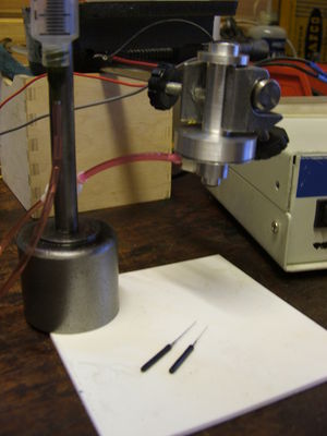
The nozzle was removed from a spray can, a pair of sharp side cutters soon released the insert, a alluminium housing was made and this then fitted into the body to allow nozzle changing, to reduce the size of hole a soldering iron was used to carefully wipe the front face of the plastic insert and then the hole reamed from the back with tapered watch reamers, (see photo) The height of the syringe body above the head is important if you want to avoid drips when it is not working, too high and it drips despite such a small hole, (the fluid is low viscosity).
The best way to describe the jet is a little thicker than a human hair, and because it is transparent very difficult to see, only by catching it in the right light with a black background can it be observed, I simply do not have the equipment or ability to catch it on camera, with a 4.2 Kh bimorph running at 6Kh and 100 volts the plotter would have to move very fast not to saturate the powder bed, to achieve a lower emission rate the voltage can be reduced but adding PWM may be better.
Lighter spark units..
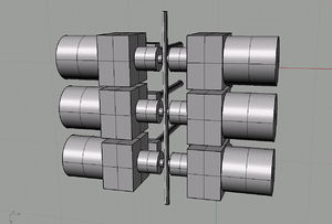
The spark units from cigarette lighters appear to consist of stacks of approx 2mm diameter 2mm long piezo material, the stack height is approx 6 to 8mm long, when connected to the drive unit used for bimorphs the displacement seems very small, it may be necessary to apply more energy to the stack than the existing drive can deliver. deposition may be possible by having two units diametrically opposed, with a very small tube between them.
ToDo
- build a drive incorporating an arduino or add pwm to existing box -- DONE see here.
- look at higher viscosity fluids, varnish, resins etc
- look for and try solvents that melt polymer powders
- heat the head and try crayons, (colours)
- try (electronic lighter) piezo slugs
- Add high frequency transformer, (may make a difference)
look at xtal's
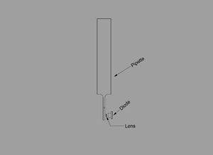
Laser pulsed bubble-jet printhead investigate the possibility of creating a bubble with laser energy. A DVD laser mounted such that the focus point is near to the centre of a thin glass tube or needle pipette filled with ink causes a bubble to form and eject fluid from the nozzle tip.
A simple test was carried out using a glass pipette with ink and a soldering iron, the iron when touched against the glass pipette resulted in ink being ejected, the response was very fast, mainly due to the thin wall of the glass and low volume of ink in the 1mm dia tube.
piezo pulsed bubble-jet printhead investigate the possibility of creating a bubble using energy produced by a mistmaker.
Sensor mode.. untried stuff.
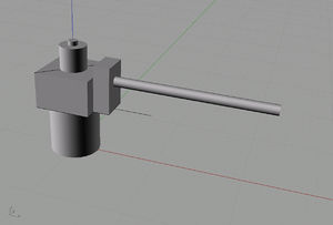
If a cross is cut on a bimorph so that we have four seperate pieces on the disc, and a wire soldered onto each segment,then attach a rod in the centre of the disc, the position of the rod can be ascertained similar to a joystick, also if we energised the segments in sequence we should be able to move the rod, it should also be possible to cut strips from the bimorph and have an array within a block to make a strip of printheads.
Some speculation... Apparently when piezo's are made the material is at an elevated temperature, (molten in the case of polymers) and 100 volts or so is applied whilst it cools, this aligns the material from positive to negative and defines the mode of vibration, what if the nozzle on a reprap and the bed could form this electrical connection so that the filament is polarized, thereby creating a part with piezo characteristics, actuators or sensors could be built right into the part. ??????
Mist maker observations...
Some years ago when ultrasonic mist makers came out it was decided to acquire one to tinker with, they must be submerged in fluid to work due to a sensor which inhibits operation when dry, there seems to be a focal point of energy about 15 to 20 mm above the transducer surface, the first observation was the pain inflicted on the finger at this focal point, indicating the intense energy produced, a plastic ruler held at the focal point melted at a spot, by moving the ruler slowly a line could be drawn, despite the fact that it was below the water surface, a sample part made by SLA was tried, the reaction was violent if held to long in one spot, but formed a discoloured line when moved faster, silicone rubber also was tried, and as it is clearer it could be observed that the energy formed a cavity below the surface which expanded if held stationary, or again if moved slowly produced a line, if held stationary the cavity grew to the surface and popped at it broke the surface, silicone rubber has a melting point around 700 deg C (check this) indicating the amount of energy produced. The mistmaker was part of an overall concept to create a mist from photo resin to be the basis of a recoater system within a vacuum chamber and use elecron beam energy to cure the resin.
Documents about piezo print heads
- Thesis_Wijshoff.pdf - "Structure - and fluid-dynamics in piezo inkjet printheads"
- Heated Piezo for Jetting Wax For ideas on a heated wax printing piezo jet
Latest forum messages
