Scratch n' Etch PCBs
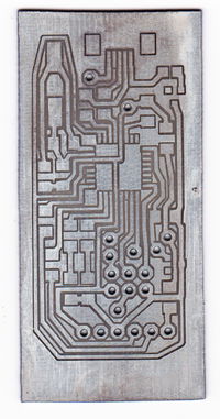
The Scratch n' Etch method for producing PCBs uses an etch resist that is scratched away with a CNC and a carbide scriber. This page documents a successful version of this method done with a 3DPrintMi and a scriber holder, and earlier on a McWire-style CNC by Matt Gilbert.
The Scratch n' Etch method is one of the more successful methods of Automated Circuitry Making.
Contents
Overview
The scratch n' etch method has been described in principle on the Homebrew PCBs Yahoo group. This page documents the Scratch n' Etch process as explained on that discussion board, with one important addition: The scriber is pressure sensitive.
The etch resist used is Dykem Layout Blue (aka "machinist's paint", "machinist's blue", or "layout paint"). This paint is used by machinists because it's designed to be easily scratched off with a carbide scriber, leaving behind a fine, precise line.
The scriber exposes copper that can be removed using your favorite etch. (Cupric chloride is a good choice because it's reusable.)
Since the scratches themselves are the areas that will be removed, you must isolate the traces and areas you want to keep by scratching around them.
Since the scratches are very thin, to get adequate isolation you have to scratch a few "laps" around each trace, sort of like a lawnmower, moving a little further out each time, scratching away a thicker line. This requires your GCode to include these "laps".
The trick to making this method reliable is to make the scriber pressure-sensitive, rather than simply calibrating a fixed "scratch height". It's not likely that the bed of your CNC and the copper-clad board you are scratching are perfectly level. Rather than attempt to level it, adding a pressure sensor allows the machine to adjust it's height as it scratches. If it starts scratching to hard, it lifts up a bit. If it's scratching too lightly, it will lower the scriber a bit.
Step-by-step
| Photo | Description |
|---|---|
| Step 1: Clean the board. Start with a copper-clad board. Clean thoroughly with steel wool and acetone. Allow a few minutes for the acetone to evaporate. | |
| Step 2: Paint the board. Paint a single, thick, even coat of Dykem Layout Blue. Using the in-cap brush seems to be the easiest way. | |
| Step 3: Scratch away the paint to expose the copper that you want to remove. This means removing the copper around a trace, isolating it. Scratch a few "laps" around the trace to make the gap wider than a single scratch, since a single scratch is likely to get bridged with solder. The GCode for this method needs to take this into account, as well as the pressure-sensitive modes. One method of producing this GCode from PCB designs will be explained in the Software section. | |
| Step 4: Etch the board with your favorite etch. (Cupric chloride is a good choice because it's reusable.) | |
| Step 5: Drill holes for through-hole components. This board was drilled with a Dremel attached to the CNC. Drill after etching to avoid etching away metal on the inner ring of each hole. | |
| Step 6: Clean off the paint with a steel wool cleaning pad and acetone. | |
| Step 7 (optional): Tin the board using Liquid Tin. Liquid Tin deposits a layer of tin over the copper, preventing the copper from corroding or oxidizing over time and making it a little easier to solder. If you skip this step, your board will probably work fine, though the copper may get a little ugly after a while, and may even stop working eventually.
Liquid Tin is very dangerous. Observe all precations when using it, such as wearing thick rubber gloves, goggles, and a mask. |
Electronics
PCBScriber
The electronics consist of an Arduino Uno and a simplified RAMPs-style shield (wiith a PCB produced by the McWire version). It has 3 polulo controllers for the 3 axes, 3 minimum endstops, 1 mroe endstop for the scriber pressure sensor, and a Dremel with a flex shaft controlled by a Powerswitch Tail II.
Older McWire Version
The electronics used for McWire version are basically the Generation2Electronics, with a couple modifications:
- A pressure sensitive resistor was added to detect how much pressure the scriber has on it.
- A Powerswitch Tail II was added to turn on and off the Dremel tool that's used to drill the holes.
Of course, these additions require changes to the GCode and CNC firmware, detailed below.
Software
Generating the G-code
The Processing code for converting PCB SVGs exported from Fritzing to gcode for scratch n' etch-ing and drilling is available on GitLab: https://gitlab.com/mattgilbertnet/svg_to_gcode_scratchnetch
The G-code used for the Scratch n' Etch method is very similar to the G-code used for isolation milling or other processes. The main differences are:
- The path must go around each trace several times, moving slightly further out each time.
- There must be a command to turn on a "pressure-sensing mode", during which the CNC will raise or lower the scriber to maintain a certain amount of pressure. (This also requires changes to the firmware of the CNC, which are explained in the CNC Firmware section.)
Voronoi-type isolation paths are interesting because they reduce the lengths of the paths, thus reducing the time required to scratch them. However, outline-type isolation paths are preffered over Voronoi-type ones, because:
- They maintain a circular pad shape which is easier to solder.
- They reduce the risk of "parasitic capacitance" from traces with larger copper areas.
- They are easier to generate programmatically.
The particular method for generating GCode may be different depending on your needs. The particular syntax explained here was created ad hoc, and may conflict with other GGode conventions.
PCBScriber Firmware
The Firmware is based on Teacup. More info on the PCBScriber page.
Older McWire Version
The firmware was written for a McWire modified to scratch with a carbide mounted with a pressure sensor to do the scratching, as well as a dremel to do the drilling. The firmware was based on a version of the Marlin firmware for an Arduino Uno.
The firmware for the older McWire version is available here: https://gitlab.com/mattgilbertnet/Scratch-n-Etch-McWire


