Sanguinololu Wireless Adapter
Release status: working
| Description | Release Version 2.0
|
| License | GPLv3
|
| Author | |
| Contributors | |
| Based-on | [[]]
|
| Categories | |
| CAD Models | Kicad
|
| External Link |
Contents
Introduction
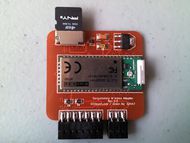
The Sanguinololu Wireless Adapter (either SWA 2.0 or SWA 1.0) allows full wireless communication with the Sanguinololu controller. Print wirelessly, or issue a command wirelessly to print from a microSD card.
Latest Updates -- 7/23/12
- SWA 2.0 released.
- SWA 2.0 has been successfully tested on revision 1.3a of the Sanguinololu, however it should function correctly on revisions 1.2 and above... except for 1.3b.
- SWA 2.0 has been successfully tested using recent versions of Sprinter and Printrun.
Important
- Connecting SWA 2.0 or SWA 1.0 to a Sanguinololu of revision 1.1 or below, may damage either or your Sanguinololu.
Where to get it?
ODDepot (fully assembled or bare PCBs)
SWA 2.0
Changes from SWA 1.0
- The RN-41 has been replaced with the WT41-A which has enhanced range (1000m according to Bluegiga, when paired with another WT41-A).
- To save board space, DIP switches have been eliminated and all components have become SMDs.
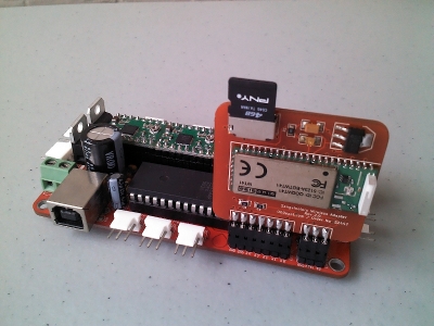
- The board no longer overhangs the Y and Z motor connectors.
Setup
WT41-A Configuration
All configuration of the WT41-A must be done in Sanguinololu firmware. However, default configuration should be sufficient. Make sure Serial1 (in Sprinter or other Sanguinololu firmware) is set to 115200 baud (usually the default setting in Sprinter). Consult the WT41-A datasheet for configuration details.
Sanguinololu Firmware
SWA 2.0 uses RX1/TX1 on the Sanguinololu for serial communication. As of this writing, a forked version of Sprinter is the only known firmware which supports SWA 2.0 without modification. If you wish to modify your favorite firmware, it may be as easy as replacing every instance of 'Serial.' with 'Serial1.' in your firmware's source code. Remember, after modification the USB cable will not function during regular USB communication with the Sanguinololu. Don't worry, the USB cable will still work with the bootloader when uploading new firmware so you can revert the code and re-establish regular USB communication at any time. If you have questions about modifying your firmware, or would like to see your firmware supported, you make contact ODDepot.com.
Sprinter
A forked version of Sprinter which supports the Sanguinololu and SWA 2.0 by default can be found here. Remember, you still need to modify Configuration.h to your specific requirements.
If you're feeling ambitious and want to modify Sprinter yourself, the following should do it:
Replace every instance of 'Serial.' with 'Serial1.' in ALL source code files, then add the following block of code to the beginning of setup() but AFTER the line 'Serial1.begin(BAUDRATE);' in Sprinter.pde:
 /*
   This code is necessary to configure the WT41 AND prevent Sprinter and iWRAP (the firmware on the WT41) from entering
   an infinite loop where Sprinter sends 'Unknown command:' and iWRAP replies with 'SYNTAX ERROR'. When this happens,
   iWRAP does not respond to a bluetooth connection attempt.
 */
 Serial1.write("PIO SETDIR FF FF\r\n");  // Set PIO direction
 Serial1.write("PIO SET FF 00\r\n");  // Set PIO output (turn LED on)
 while(1){
   // Flush everything in the receive buffer.
   while(Serial1.available()){
     Serial1.read();
   }
   // Send string to the WT41 and wait for a reply (if there is one).
   Serial1.write("WT41 intialized\r\n");
   delay(1000);
   // If the WT41 has entered data mode (it will once a bluetooth connection is established) there won't be a reply.
   if(!Serial1.available()){
     break; // Break the while loop and continue on.
   }
 }
 /*
   From this point on, data sent from Sprinter should pass through the WT41 seamlessly to the host software and vice versa.
 */
Indication
SWA 2.0 has only one LED which confirms the WT41-A is powered up and accepting commmands from the Sanguinololu firmware.
Connecting
Make sure the Sanguinololu has power disconnected. Insert SWA 2.0 as seen in the image below. Reconnect power to the Sanguinololu.
Ubuntu
Command Line
In a terminal type something like:
hcitool scan
You should see something similar to:
 Scanning ...
         00:07:80:46:87:5A        WT41-A
In this case, 00:07:80:46:87:5A is the address of the WT41-A. Naturally, your address will be different. Copy the address, you will need it below.
Now type something like:
sudo rfcomm connect rfcomm0 <WT41-A address> 1
Make sure to replace <WT41-A address> with the address you copied from above.
If a serial connection is successfully made you should see something like:
 Connected /dev/rfcomm0 to <WT41-A address> on channel 1
 Press CTRL-C for hangup
You will now be able to connect to the Sanguinololu with the host software of your choice. Be sure to specify the connection port as /dev/rfcomm0 or whatever you used above.
SWA 1.0
Setup
RN-41 Configuration
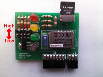
SWA 1.0 has the option for a 4 pole DIP switch when selecting between different modes on the RN-41. Omitting the dip switch will keep the RN-41 in it's default state, which is usually sufficient for operation. In the picture below, the switches labeled 1-4 correspond to pins PIO7, PIO6, PIO3 and PIO4 respectively on the RN-41. The 'up' position is high (3.3V) and the 'down' position is low (GND).
Switch 1 (PIO7) controls the baudrate. High corresponds to 9600 baud and low to 115200 baud. For details on the other modes consult the RN-41 datasheet.
Sanguinololu Firmware
SWA 1.0 uses RX1/TX1 on the Sanguinololu for serial communication. As of this writing, no known firmware supports SWA 1.0 'out of box' without some modification. Using Sprinter, this is relatively easy to do if you are familiar with uploading firmware. Firstly, find the following three files:
- Sprinter.pde
- SdFatUtil.h
- SdFile.cpp
Then, with your favorite text editor replace each instance of 'Serial.' with 'Serial1.' in every file. Finally, compile and upload to the Sanguinololu. After modification, the USB cable will not function during regular USB communication with the Sanguinololu. Don't worry, the USB cable will still work with the bootloader when uploading new firmware so you can revert the code and re-establish regular USB communication at any time.
Indication
- D1 (Green LED)
- Slow blinking: RN-41 is in sleep mode.
- Fast blinking: RN-41 is ready to be paired.
- Constantly on: Serial connection established.
You will not be able to pair the device in sleep mode. When this happens (and it will after about 1 minute) you should press the reset button on the Sanguinololu to 'wake up' the RN-41. If the RN-41 is already paired and the LED is in this state, you shouldn't have a problem establishing a serial connection.
- D2 (Yellow LED)
- Serial connection established.
- D3 (Red LED)
- Power applied / microSD card inserted
D3 was intended to be a microSD card detect indicator. However, the terminals for this function on the microSD card socket have proven to be too difficult to solder by hand. Luckily, it can also serve as a 3.3V power indicator if pad 11 is soldered to pad 10 on the microSD socket footprint (this is the usual outcome anyway if you're not precise enough). The power indicator function has proven to be more useful when testing SWA 1.0.
Connecting
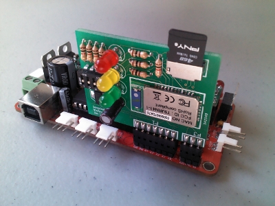
Make sure the Sanguinololu has power disconnected. Insert SWA 1.0 as seen in the image below. Reconnect power to the Sanguinololu. When power is applied, D1 (Green LED) should start fast blinking.
Ubuntu
Command Line
In a terminal type something like:
hcitool scan
You should see something similar to:
 Scanning ...
         00:06:66:07:DA:76        FireFly-DA76
In this case, FireFly-DA76 is the name of the RN-41 onboard SWA 1.0 and 00:06:66:07:DA:76 is it's address. Naturally, your name and address will be different. Copy the address, you will need it below.
Now type something like:
sudo rfcomm connect rfcomm0 <RN-41 address> 1
Make sure to replace <RN-41 address> with the address you copied from above.
If a serial connection is successfully made you should see something like:
 Connected /dev/rfcomm0 to <RN-41 address> on channel 1
 Press CTRL-C for hangup
You should also see that D1 (Green LED) and D2 (Yellow LED) are now constantly on. You will now be able to connect to the Sanguinololu with the host software of your choice. Be sure to specify the connection port as /dev/rfcomm0 or whatever you used above.
GUI
If you would like to use a GUI the default bluetooth manager is not recommended. Instead, use Blueman Device Manager by searching Synaptic for 'blueman' or by typing the following in a terminal:
sudo apt-get install blueman
You may need to start it manually the first time after installing. If you can't find it, restart your computer. It should appear on your panel (as a second bluetooth icon). After you have it up and running do the following:
- Find 'Search' and click
- 'Firefly-XXXX' should be listed as a device
- Right click on 'Firefly-XXXX' and select 'Pair'
- Type '1234' in the input dialog that appears then click 'OK'
- Right click again and select 'Setup...'
- Select 'Serial Port' and click 'Forward'
You should see a message in the top right of your screen. It's important that you notice this and the port location (which is typically '/dev/rfcomm0'). You should also see that D1 (Green LED) and D2 (Yellow LED) are now constantly on. You will now be able to connect to the Sanguinololu with the host software of your choice. Be sure to specify the connection port as /dev/rfcomm0 or whatever you saw above. Note, Blueman Device Manager may be buggy if you lose the connection or disconnect and try to reconnect immediately afterwards.
Windows 7
A successful pairing has been made with the RN-41 onboard SWA 1.0, but no further testing has been done.
Android
A successful pairing has been made with the RN-41 onboard SWA 1.0 using a Pantech Pocket, but no further testing has been done.


