RAMPS 1.7/ru
|
English • العربية • български • català • čeština • Deutsch • Ελληνικά • español • فارسی • français • hrvatski • magyar • italiano • română • 日本語 • 한국어 • lietuvių • Nederlands • norsk • polski • português • русский • Türkçe • українська • 中文(中国大陆) • 中文(台灣) • עברית • azərbaycanca • |
Состояние выпуска: Прототип

| Описание | |
| Лицензия | |
| Автор | |
| Соавторы | |
| На основе | |
| Категории | |
| CAD модели | |
| Ссылка на внешний ресурс |
Резюме
Я работаю над разработкой версии RAMPS, которая позволит применять драйвера TMC2130 (используя SPI), просто путем перестановки некоторых джамперов
Это ссылка на форумы обсуждения платы
Плата также предназначена для использования с 32-разрядными процессорами, которые используют 3В логику, вроде Arduino DUE
PCB
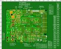
Последняя версия
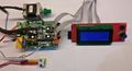
Тест использующий Due

Нажмите на любое изображение для увеличения размера
Источники
Прошивка
Очень предварительное тестирование прошивки
- Для Arduino Mega, основанная на Marlin bugfix-1.1.x для RAMPS_1.7 на GitHub (до сих пор используется название и настройки 1.4, но номера контактов 1.7 в файле pins_RAMPS.h)
- Для Arduino DUE и Mega, основанная на Marlin bugfix-2.0.x для RAMPS_1.7 на GitHub
Файлы проекта
Как только я узнаю, что конструкция вообще работает, все файлы у меня есть/будут доступны для использования.
Пока о PCB RAMPS 1.7 GitHub repository
Схемы
На этой Вики схемы будет представлены в качестве картинок.
Для pdf-версий см.: Repository на GitHub
Цепь стола подогрева

Нажмите на картинку для увеличения размера.
Ссылка на pdf версию на GitHub
12В & 5В шины

Нажмите на картинку для увеличения размера.
Ссылка на pdf версию на GitHub
5В питание на плате
It is possible (recommended) to add an on-board DC-DC converter, for additional 5V power on the board.
The Arduino Mega on-board 5V regulator is known to over heat (causing ramdom resets) if it is used to also power 5V add-on to the RAMPS boards.
The Arduino DUE has on-board regulators for both 3.3V and 5V power, but the DUE regulators can handel even less power than the Mega regulators.
So for these reasons it is recommended to use the sockets provided on the RAMPS 1.7 board, to add a DC-DC regulator, so additional 5V power can be available. The sockets are very well suited to be used with the MP1584 adjustable DC-DC switch mode regulators. But any other regulator board may also be used/made-to-fit.

Нажмите на картинку для увеличения размера.
Ссылка на pdf версию на GitHub
Заметьте - джампер J2 в правом углу

Нажмите на картинку для увеличения размера.
Заметьте - джампер J2 в правом углу

Нажмите на картинку для увеличения размера.

Нажмите на картинку для увеличения размера.
Как только я настрою MP1584 DC-DC преобразователь на 5В, я обычно горячим клеем фиксирую подстроечный резистор.
Джамперы & Aux-разъемы
Джамперы шагового двигателя


AUX-разъемы
Aux-1


Aux-2


Aux-3
Aux-4
Aux-5
Aux - Не нумерованные
Сервопривод

- S0 - Сервопривод 0
- Arduino контакт D4
- Альтернативное применение: нет
- S1 - Сервопривод 1
- Arduino контакт D5
- Альтернативное применение: нет
- S2 - Сервопривод 2
- Arduino контакт D6
- Альтернативное применение: С TMC2130 как SPI E1_Chip_Select (E1cs)
- S3 - Сервопривод 3
- Arduino контакт D7
- Альтернативное применение: С TMC2130 как E1_Diagnose_1 (E1cf)
Jumpers and options
Спецификация
(Частично) список компонентов, которые используются для этой платы.
| ID | Описание | Количество | Digikey Part Number (Description) | Другой поставщик | Примечания |
|---|---|---|---|---|---|
| C1 | Низкий ESR 100uF/35V | 6 | PCE4554CT-ND | ? | 6.60мм x 6.60мм |
| C2 | 10uF/16V | 3 | 399-17336-1-ND | ? | 4.30мм x 4.30мм |
| C3 | 1-10uF / 6V / 0805 | 1 | CAP CER 10UF 6.3V X5R 0805 | ebay option | 0805 |
| C6 | 100nF / 6V / 0805 | 8 | CAP CER 0.1UF 50V X7R 0805 | ebay option | 0805 |
| C7 | 1-10uF / 35V / 0805 | 1 | CAP CER 10UF 35V X5R 0805 | ? | 0805 |
| C8 | 10uF/35V | 1 | 732-8503-1-ND | ? | 4.30mm x 4.30mm |
| Q3,Q4 | IRLB3034 N-channel mosfet, 2 mili Ohm, 40V |
2 | IRLB3034PBF-ND | ? | TO-220 |
| Q3,Q4 Alternative | IRLB8743 N-channel mosfet, 4 mili Ohm, 30V |
2 | IRLB8743PBF-ND | ? | TO-220 |
| Q1, Q2 | IRLR7843 N-channel mosfet, 4 milli Ohm, 30V |
2 | IRLR7843PBFCT-ND | ? | TO-252 |
| N | AO3400 N-channel mosfet, 33-52 milli Ohm, 30V |
4 | 785-1000-1-ND | ? | SOT-23 |
| IC | 74LS125 | 1 | SN74LS125ADR | ebay option | 14-SOIC (0.154", 3.90mm Width) |
| IC | 24LC256 | 1 | 24LC256 | ebay option | 8-SOIC (0.154", 3.90mm Width) |
| S1 | 4-контактные 7.62мм винтовые клеммы | 1 | ?d | ?o | ?n |
| S2 | 2-контактные 5.08мм винтовые клеммы | 4 | ?d | ?o | ?n |
| R1 | 100K 0805 | 10 | Digi option | ebay option | 0805 |
| R2 | 10K 0805 | 6 | ?d | ?o | 0805 |
| R3 | 4K7 0805 | 13 | ?d | ?o | 0805 |
| R4 | 2K2 0805 | 7 | ?d | ?o | 0805 |
| R5 | 10R 0805 | 6 | ?d | ?o | 0805 |
| R6 | 1K 0805 | 1 | ?d | ?o | 0805 |
| R7 | 680R 0805 | 1 | ?d | ?o | 0805 |
| E1-3 | Зелёный светодиод 0805 | 3 | ?d | ?o | 0805 |
| E4 | Красный светодиод 0805 | 3 | ?d | ?o | 0805 |
| E5 | Жёлтый светодиод 0805 | 1 | ?d | ?o | 0805 |
| D2 | diode 1N5822 TH | 1 | 1N5822G | ebay options | Any 3-10A diode will do fine |
| D1, D3-D5 | diode 1N4007 smd | 4 | DIODE SCHOTTKY 30V 1A DO214AA | ebay options | Housing: DO-214AA / SMB |
| Diode | 1N5819 / S4 - smd | 5 | Digi Options | ebay options | SOD-123 or "DO-213AB, MELF (Glass)"
|
Fuse options
| ID | Описание | Количество | Digikey Part Number (Description) | Другой поставщик | Примечания |
|---|---|---|---|---|---|
| F1,F2 | Auto blade fuse / 1808 | 2 | ?d | ?o | ?n |
| F3 | TH fuse / 0603 fuse | 1 | ?d | ?o | ?n |
| F4,F5 | Is currently a "PCB-wire fuse", but will not protect the mosfets, only the rest of the PCB wires options are: 1206,24V, 2A poly fuse |
2 | ?d | ebay example | ?n |
Pin headers
| ID | Описание | Количество | Digikey Part Number (Description) | Другой поставщик | Примечания |
|---|---|---|---|---|---|
| 2p male | txt | ? | ?d | ?o | ?n |
| 3p male | txt | ? | ?d | ?o | ?n |
| 1 row x 8p female | txt | 10 | ?d | ?o | ?n |
| 1 row x 2p female | txt | 12 | ?d | ?o | ?n |
| 2 row x 2p female | txt | 2 | ?d | ?o | ?n |
| 1 row x 4p female | txt | 1 | ?d | ?o | ?n
|
Board assembly
I always find it easiest to solder in the smallest and lowest components first.
Once all components are soldered to the top, then it is advisable to solder in the pins on the bottom, that connects the shield to the Arduino. Because once the top-pins, jumpers and headers are soldered, it becomes very difficult to reach the solder points for the bottom pins, with the soldering iron, without also melting some of the header plastics.
Места плотного соприкосновения
Чип 74LS125

I find that it is easier to solder the chip, before too many components are placed around it.
Диод D2

Place the little (round) capacitor as close to the 74LS125 chip as possible, and as far back from the D2 mounting hole as possible.
Likewise place the larger (round) capacitor as far back from the D2 mounting hole as possible.
Температура

It might be easier to first solder the capacitors, and then the three (R3) resistors.