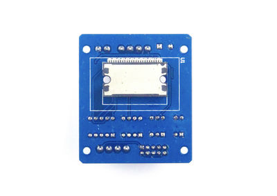
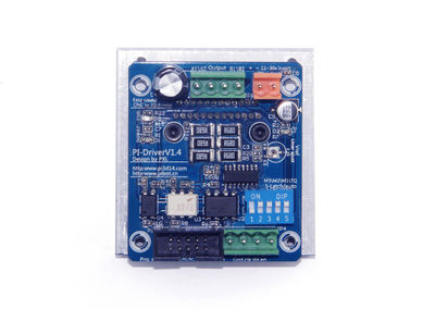
PiBot TB6600 Stepper Driver
|
English • العربية • български • català • čeština • Deutsch • Ελληνικά • español • فارسی • français • hrvatski • magyar • italiano • română • 日本語 • 한국어 • lietuvių • Nederlands • norsk • polski • português • русский • Türkçe • українська • 中文(中国大陆) • 中文(台灣) • עברית • azərbaycanca • |
Release status: working
| Description | Part of PiBot Electronics,Stepper Driver
|
| License | |
| Author | |
| Contributors | |
| Based-on | [[]]
|
| Categories | |
| CAD Models | see #How to Build
|
| External Link |
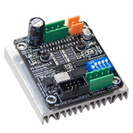
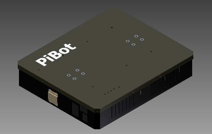
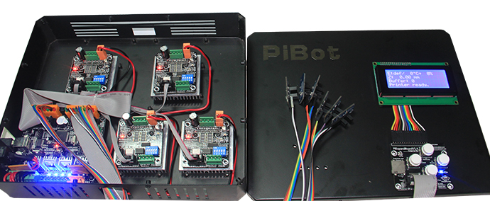
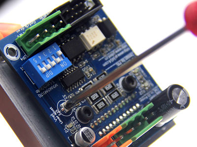
- PiBot TB6600 Stepper Driveris a part of PiBot electronics. It put forward a easy solution to make your 3D printer and CNC machine. Not only an electronic board, but also an PiBot-box which's function is similar to the computer Host and you can easily handle it only plug few terminals.
Contents
Description
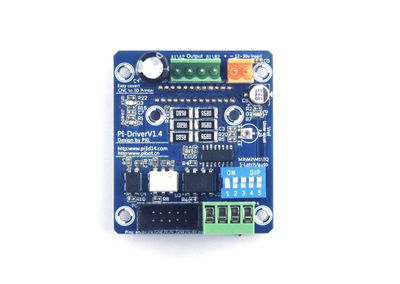
The PiBot TB6600 Stepper Driver is a TOSHIBA TB6600HG based driver.
- Features of stepper Driver
- PWM chopper-type single-chip bipolar sinusoidal micro-step stepping motor driver.
- BiCD 0.13 (50 V) process, Lower Ron: 0.4 Ω(typ.).
- Output withstand voltage: VCC = 50 V.
- Output current: IOUT = 5.0 A (absolute maximum ratings, peak, within 100ms);IOUT = 4.5 A (operating range, maximal. value);More Stepper motors you can choose (NEMA17,NEMA23 and a few NEMA34). weld 6*1W external resister sensor.
- Thermal shut down (TSD) protection.
- Under voltage lock out (UVLO) protection.
- Over-current detection (ISD) protection.
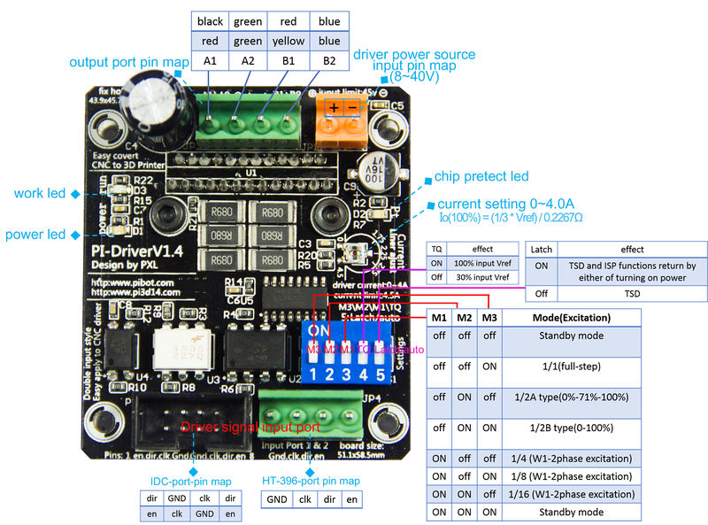
- Double input port: Anti-reverse structure IDC haeder( 8pin symmetrical input) & HT-396-4pin input (suit for DIY).
- Stepless adjustable reference voltage.
- Compatible the CNC Stepper Motor.
- Offer an solution to change your CNC to 3D Printer.
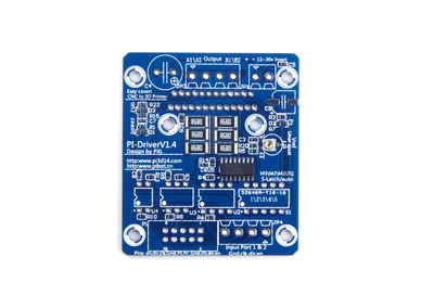
- Board size: 51.1*58.5mm ; fix hole: 43.9*45.7mm -Carry 60*60*10mm aluminum Heat sink which build-in fix hole and connection hole.
- Auto half current, energy conservation.
- Photoelectric-isolation used in the input port,compatible more drive Level.
- Programmable micro step - 1/1, 1/2A, 1/2B, 1/4, 1/8, 1/16.
- Affordable price.
- For purchasing or more information, please contact PiBot, or one of the resellers.
- Any idea to develop this motor driver, you can ask [Pan Xinlong].
- All parts are licensed under CC BY-NC-SA 3.0 .
Driver Connection and PiBot Box Use
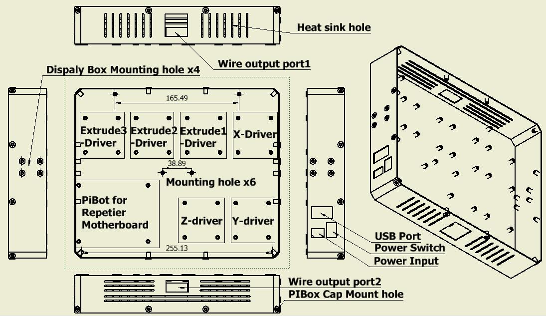
The second generation of PiBot Box will put forward which can include 6 motor driver and the Manual Controller.
Settings of Driver
PiBot TB6600 Stepper Driver all input pins build-in connect to GND with a 100KΩ resistance.
| M1(input) | M2(input) | M3(input) | Mode (Excitation) | Illustrate |
| L | L | L | standby mode (operation of the internal circuit is almost turned off) | H-High voltage, L-Low voltage |
| L | L | H | 1/1(2-phase excitation, full-step) | |
| L | H | L | 1/2A type (1-2phase excitation A type) (0%-71%-100%) | |
| L | H | H | 1/2B type (1-2phase excitation B type) (0%-100%) | |
| H | L | L | 1/4 (W1-2phase excitation) | |
| H | L | H | 1/8 (2W1-2phase excitation) | |
| H | H | L | 1/16 (4W1-2phase excitation) | |
| H | H | H | standby mode (operation of the internal circuit is almost turned off) |
| Auto\Latch(input) | Effect | Illustrate |
| L | TSD and ISD functions return by either of turning on power supply again or
programming the ENABLE as H → L → H || default set to High | |
| H | TSD and ISD functions return automatically |
| TQ(input) | Vref Voltage Ratio | Effect | Illustrate |
| L | 30% of the input Vref | decrease 70% Motor current | default set to High |
| H | 100% of the input Vref | full current,more power |
100% Current Settings (Current value)
100% current value is determined by Vref inputted from external part and the external resistance for detecting output current. Vref is doubled 1/3 inside IC. Per the [TB6600 datasheet], the calculation for current is:
Io(100%) = (1/3 × Vref) ÷ RNF
The average current is lower than the calculated value because this IC has the method of peak current detection.
RNF should be 0.68||0.68||0.68=0.2267Ω
Sometimes this value can be set by experiment, that Stepper motor not heating, small noise and the chip do not get too hot.
How to Build
- Related Files
- Solder Images
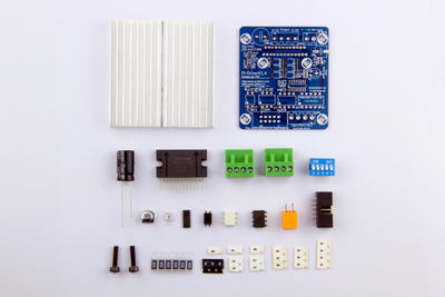
- Prepare all of the components to build a PiBot TB6600 Stepper Driver;
- You'll need a soldering toolkit and SMT soldering toolkit to finish this board.
- Use SMT soldering toolkit
- Apply solder paste to every exposed SMD pad.
- Place each SMD component on its appropriate pad.
- Place populated board on a cold hotplate,turn hotplate on,board solders itself!
- Solder in remaining through hole components.
- If you without a soldering toolkit, you can also use an tweezers and an soldering iron finish them by manual.
- Use soldering toolkit
- Insert through hole components.
- solder all these pins to the pad.
- Solder the TB6600 in bottom
- Be careful, please ensure no short cut and insufficient solder.
- Test
- Before plug in the power source, you first need to check the polarity of electrolytic capacitor, chip and diode.
- Use an digital multimeter to test the resistance value of the power. Usually, it has a increase resister. Ensure no short cut and insufficient solder.
- Now, you can plug in the power source, the power LED (red) lighten. Usually,the Run LED(green or red) lighten(it not related).
- Connect the control pins and output pins(A1-Red A2-Green B1-Yellow B2-Blue or A1-Black A2-Green B1-Red B2-Blue), input signal,
- stepper Motor and Driver Connection
| A1(output) | A2(output) | B1(output) | B1(output) |
| Red wire | Green wire | Yellow wire | Blue wire |
| Black wire | Green wire | Red wire | Blue wire |
Pin Map
- Input, The IDC Header
| Pin | Name | Function |
| 1 | Enable | Control signal input. set to high input, set to low disable input. |
| 2 | direction | Forward/reverse control. set to high CW, set to low CCW. |
| 3 | clk | A pulse on this line will make the stepper motor advance one step in the desired direction. |
| 4 | GND | Connect to the controller common ground. |
| 5 | GND | Connect to the controller common ground. |
| 6 | clk | A pulse on this line will make the stepper motor advance one step in the desired direction. |
| 7 | direction | Forward/reverse control. set to high CW, set to low CCW. |
| 8 | Enable | Control signal input. set to high input, set to low disable input. |
- Input, HT-3.96mm-4pin header
| Pin | Name | Function |
| 1 | Enable | Control signal input. set to high input, set to low disable input. |
| 2 | direction | Forward/reverse control. set to high CW, set to low CCW. |
| 3 | clk | A pulse on this line will make the stepper motor advance one step in the desired direction. |
| 4 | GND | Connect to the controller common ground. |
- Input, HT-3.96mm-2pin header
| Pin | Name | Function |
| 1 | Power + | Input the power source "+" polarity. Limit input:0-45V. |
| 2 | Power - | Input the power source "-" polarity. |
- Output, HT-3.96mm-4pin header
| Pin | Name | Function |
| 1 | A1 | Output of Driver connect to Stepper motor A1-A2 |
| 2 | A2 | Output of Driver connect to Stepper motor A1-A2 |
| 3 | B1 | Output of Driver connect to Stepper motor B1-B2 |
| 4 | B2 | Output of Driver connect to Stepper motor B1-B2 |
Developments
- PiBox has been put forward. It is made of steel plate, which can contain 1 to 6 drivers and with a good heat sink effection.
- You can change the connection of the 74HC123D's output pin to the TQ pin(the 3rd pin of TB6600 chip).
- The new driver design will use the single pin header out going the setting table, so that you can program to them.
