Optical encoders 01
Release status: unknown

| Description | Linear Optical Encoder Components
|
| License | unknown
|
| Author | |
| Contributors | |
| Based-on | |
| Categories | |
| CAD Models | |
| External Link |
Contents
Overview
For those who enjoy scavenging, many components useful for constructing 3D printers can be found in inkjet printers. This often includes optical encoders and strips. This page gives information on finding and using these items.
Finding printers with linear optical encoders in them
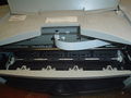
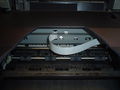
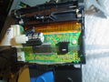
Cheap inkjet printers can be obtained from garage sales or recycling centers. Do not get laser printers, since they do not have the right optical components in them. Not all inkjet printers have optical encoders and strips in them. It is easy to tell by opening the lid (as if to change the ink). You should see a grey plastic strip close to the shiny metal rod and running parallel to it. The printers that people sell cheaply or recycle generally are somewhat inky inside. Do not get ink on the optical strip, though you may be able to clean it off.
The strip runs through the optical sensor, which may be quite hidden. It is probably on the back side of the assembly that holds the ink cartridges.
The pictures below show two inkjet printers (both Dell) with the covers open. The gray encoder strips are visible.
Optical strip identification
Optical strip identification


Removing strips and sensors
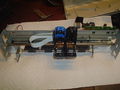
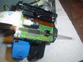
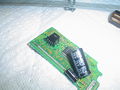
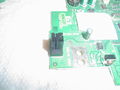
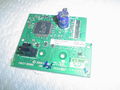
The following pictures show a partially disassembled printer with the strip and encoder (sensor).
Sensor example 1
Sensor example 2

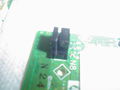
After you have removed the moving assembly you should be able to see the optical sensor. It will have a black plastic case with a slot for the strip. It will be soldered to a small printed circuit board. Do whatever you have to in order to get this circuit board free of everything else without damaging the sensor. Unsolder the sensor from the circuit board. It will have either 4 or 6 pins. If it has six pins, the pins will be in a group of 4 and a group of 2. The following are common desoldering techniques.
a. Make a big blob of solder that covers all 4 pins and will stay molten long enough that the sensor can be pulled free of the board (because all 4 pins are loose at the same time).
b. Remove the solder from around the pins with a solder socking device or solder wick.
c. Since you do not care about the circuit board, nibble away at it (but not with your sharpest wire cutters) until the pins are separated from each other and they can be unsoldered from the circuit board remnants one at a time.
Sensor example 3
Sensor example 4
Sensor example 5
Sensor example 6
Sensor example 7


Linear strips vs. circular strips
Note that some of the high end HP photoprinters use optical encoders for rotating the paper feed drum. There will be a circular encoder strip, as shown below. Lower end printers just use a small stepper motor for moving the paper.
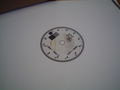
Circular strip
Linear strip


Determining encoder pinouts
The best approach is to figure out the manufacturer and part number of the unit and get the manufacturer's data sheet. However, it can be difficult to find data sheets on the optical encoders or even sometimes to figure out their manufacturer or part number. In this case it is possible to use a voltmeter in 'diode' mode to figure out which pins do what. Make a drawing of the unit with the pins identified, then make a table with a row and column for each pin. Use your voltmeter in 'diode' mode and record what is measured for each pair of pins. If the meter reading does not change form what it is when no connection is made, record it as OL. Note that a pair of pins may give different readings depending on which one connects to the positive (red) probe of the meter so it is important to take readings in both directions. Below are pictures of 5 encoders and corresponding measurement tables.
If the unit has a group of two pins and a group of four, then the group of two is the LED that shines light through the strip (it will almost certainly need a current limiting resistor, 200 ohms would be about right). The group of four has two pins for the output signals, one ground pin, and one power pin (5V in all the data sheets that I have seen).
If the unit has only four pins, the LED will be internally connected to the ground and power pins through an internal current limiting resistor.
The two output pins are the ones that give nearly identical readings with respect to the other pins (they perform the same function, differing only in the physical location of the sensor). The ground pin will show a reading of approximately 0.5 to 0.7 when it is positive with respect to the other pins (you are effectively reversing the power to the device in a safe way, so it looks somewhat like a short circuit).
Note that the Agilent ones seem to have a standard pinout.


