Motor FAQ
Contents
Introduction
This page tries to answer most of the frequently asked questions related to the choice and operation of drive motors used by the Reprap.
Stepper motors vs Servo Motors vs DC Gear Motors
Electric motors all start with a simple concept. You apply an electric current to a coil, and it generates a magnetic field. That field causes the shaft attached to rotate. This is all an electric motor is. Through some engineering, variations on this have been created to allow some further control.
DC motors
DC (Brushed) motors= easiest to use, just connect straight to battery, only two wires. Hardest to control, you need an external feedback mechanism (optical or magnetic encoder, linear encoder, etc) and H bridge motor driver to get variable speed and direction.
BLDC motors
BLDC (Brushless DC) motors= synchronous electric motors powered by direct-current (DC) electricity and having electronic commutation systems.[1] Similar to stepper motors, they need a dedicated electronic driver to run at all. Nevertheless commonly used in some applications (milling spindles, model airplanes), because they're powerful for their weight, relative silent and can reach very high RPM.
DC gear motors
A DC gear motor is a DC motor which has an extension built on to it to "gear down" the rotation. Essentially, a series of gears to make the rotation of the motor move more slowly for particular uses. DC gear motors are normal DC motors which have been geared down to decrease their speed and increase their torque. The Solarbotics GM series are a popular type because of their low cost, however the plastic gears means this comes at a price. They include a torque limiting slip clutch to protect the plastic gears. If this clutch is disabled, the gears may break.
MagServo is a highly experimental attempt to replace the stepper motors (and their drivers) in a RepRap with low-cost DC gear motors (and their drivers and a feedback mechanism).
The original Darwin design uses DC gear motors in the extruder.
Nophead reports that his DC gear motor extruder has higher throughput than other extruders. See Nophead's Extruder Tweaks.
"One project on my list of "stuff to do" is to make a small "add on board" that has the same footprint as the widely used Pololu stepper driver board. This board would receive step/direction signals from the Arduino, and then control a dc motor + encoder accordingly, as though it were a stepper motor. I call it a "stepper emulator". I have a working circuit from another project I'd like to use, but the form factor is wrong, so the board needs to be redesigned..." -- MattMoses
Another name for "stepper emulator" is GearMotorStepper.
Servo motors
Servo motors include a closed loop feedback system usually involving an optical or magnetic rotary encoder (see Motor control loop). Higher torque than comparable steppers. The difference between a servo motor and a DC gear motor is 2 factors: servo motors usually have their drive circuitry incorporated at least, but always include a rotary encoder. They also have lightweight rotors which allow them fast wind up/wind down acceleration.
Hobby servo motors
Hobby Servo Motors are standardized servo motors intended for robotics, RC, and other hobby applications. They generally will offer higher torque than comparable steppers. Servo motors use three wires, Ground, Power, and PWM. Hobby Servos are controlled by the PWM/pulse-width-modulation signal. The pulse width of the signal determines the point the servo will move to. Typical RC servos use a closed loop feedback system consisting of a potentiometer that measures the servo's current position, and electronics that drives the DC motor. The setup limits movement range to about 180 degrees typically.
In terms of a reprap, a servo would need to either be modified or purchased as a full or continuous rotation servo. However, RC servos using that configuration do not feature the closed loop feedback system anymore - the potentiometer is removed. Thus, they allow roughly setting the rotation speed but do not allow reading exact position information. Consequentially, for use in a reprap, an optical or magnetic rotary encoder has to be added to a continuous rotation servo to allow reading the servo's absolute position.
- The OpenEncoder OpenServo project is converting low-cost analog hobby servos into digital servos, using a hall sensor to get position information.
- The Servo-Stock uses a similar approach.
- dcservo expands Servo-Stock to serve as drop-in replacement for a stepper and stepper driver.
- The ServoStrap uses a servo motor and reads position information using a timing slit strip taken from a standard printer.
See Motor control loop for other projects.
Stepper Motors
- Main page: StepperMotor.
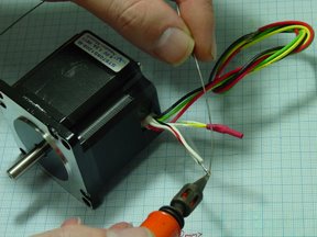
A stepper motor is another kind of special motor. This motor is powered and sent a signal to move forward x number of "steps". The current RepRap printer uses a common NEMA 17 stepper motor, which usually has 180 steps in it. These are operated in an "open loop". Stepper motors have 4 to 8 wires, and require a more complicated with two or four phases.
Stepper motors move a known interval for each pulse of power. These pulses of power are provided by a stepper driver and is referred to as a step. As each step moves the motor a known distance it makes them handy devices for repeatable positioning.
Nearly all RepRaps and RepStraps use stepper motors; see StepperMotor for details.
general motor information
The power of a motor is usually proportional to the physical size of the motor. The Darwin version of Reprap primarily used NEMA 24 stepper motors, whereas the Mendel version is designed to use either NEMA 14 or NEMA 17 motors. The more commonly used size is NEMA 17 as it is easier to find NEMA 17 motors with sufficient torque compared to NEMA 14.
Torque
The Mendel officially requires 0.137Nm torque (1400 g-cm or 1.215 lb-in) for the X, Y and Z axis. Recent designs for extruders (ExtruderController) almost exclusively require stepper motors as well, but no requirements for torque has been given in those designs.
Stepper motors do not offer as much torque or holding force as comparable DC Servo motors or DC Gear motors. Their advantage over these motors is one of positional control. Whereas: DC motors require a closed loop feedback mechanism, as well as support circuitry to drive them, a stepper motor has positional control by it's nature of rotation via fractional increments.
design tips
Standard electric motors like DC motors have a (roughly) linear torque vs. speed characteristics.
Stepper motors running with a current chopping driver on a higher supply voltage than their nominal voltage have roughly constant torque up to some speed, then they follow other types of electric motors. A lower nominal voltage extends this constant torque range, but also lowers general torque. Doubling supply voltage also doubles the range of constant torque. If the constant torque range is sufficient with a moderate supply voltage, raising supply voltage has no substantial effect. See also: Stepper torque.
Many people characterize an electric motor by two numbers at the extreme endpoints of that graph: its locked rotor torque (stall torque), and its no-load angular velocity (speed in RPM).
(The maximum output power point of a motor is (approximately) halfway between these points -- you can multiply half the locked rotor torque by half the angular velocity. It's possible to use a bunch of unit conversions to give you the mechanical output power in Watts or horsepower, but most people don't bother -- they simply convert torque to their favorite units and speed to their favorite units, and measure motor power as a combination of the two -- Nm*RPM or gm*cm*RPS or lb*in*RPM or the like).
The power you want is the torque you want multiplied by the speed you want. After ruling out all the motors that are above your budget and the ones that are below your desired power, occasionally there are no motors remaining -- so you will have to compromise somewhere -- either pay more for a more powerful motor, or run slower than you originally planned, or somehow change the design of the rest of the system to reduce the torque needed.
If you are lucky enough that the torque you need at the speed you want is "below" that torque vs. speed line of a motor, then you can directly connect that motor to your system -- no gears necessary.
Alas, most of the time all the "reasonably priced" motors with adequate power have far less torque than you need at that speed, and far less speed than you want at that torque. Fortunately, as long as that motor has the power you need, you can use gears to trade off speed and torque such that, in operation, the output of the gears gives you your desired speed and torque. (At that point, the motor is running closer to its maximum output power point).
The "gear design" page has some tips on how to do that.
Usually people end up using a motor with far more power capacity than ever gets turned into useful work, for 4 reasons:
- In addition to the power that goes into useful work, some power is needed to overcome various inescapable losses -- gear train inefficiencies, sliding friction, etc.
- A spur gear is typically over 95% efficient; a herringbone gear is more efficient; a worm gear is often worse than 50% efficient.
- people use some convenient gear ratio, rather than the hypothetical "exact" ratio that converts the speed at maximum power (half the no-load speed) into the desired output speed.
- Motors that are pushed to their limits may get hot enough to soften plastic mounting brackets.
- In the first prototype, we used motors with many times our original rough estimate of the power we needed, because we had so many uncertainties. We haven't yet figured out exactly the worst-case condition that uses the most power, or measured precisely the worst-case maximum power. Many people people prefer to stick with the "known-working" motor or one with equivalent specs.
What is a good rule of thumb to estimate how much torque and power a new RepRap design really needs?
Does the rule of thumb at Massmind: Estimating Stepper Motor Size work for RepRaps/RepStraps?
friction
This page has been flagged as containing duplicate material. An editor has suggested merging this page or section into lubrication. (Discuss)
Most the electrical power fed into the motors of any CNC machine is lost due to friction. There are a variety of techniques used to reduce friction:
- FTIStrap mentions silicon oil on the threaded rods
- lots of roller bearings
- "Peter" uses Kapton tape on the sliders
- Development:Lego RepStrap mentions vaseline on the worm gear
- ??? teflon tape ???
- managing your filament mentions oiling the filament to reduce friction inside the hot end
- PTFE Sleeve Nozzle mentions using a teflon sleeve to reduce friction inside the hot end
(There are some cases where we want to increase friction -- in particular, when two parts touch and are *not* supposed to slide against each other, such as the nuts and bolts holding the machine together, lots of friction helps keep them from unscrewing themselves).
Further reading
- Category:DriveTrains discusses various ways to convert the rotary motion of a [motor] to more useful motions.
- Actuator Fabrication has some notes on the possibility of fabricating motors (or other actuators) from simpler materials, a big step towards a fully printable reprap.
- Motor control loop
- Most motors can also be run "in reverse" as generators, which may be useful in a Wind Turbine.