Motherboard 1 1
This page describes something which is no longer the most recent version. For the replacement version see: "Official" Electronics
Contents
- 1 Motherboard v1.1
- 1.1 Overview
- 1.2 Hacks
- 1.3 Get It!
- 1.4 Files
- 1.5 Interface
- 1.6 Circuit Board
- 1.7 Components
- 1.8 Build Process
- 1.8.1 1. Apply Solder Paste
- 1.8.2 2. Place Components
- 1.8.2.1 R16 - 180 ohm resistor (181) - OPTIONAL
- 1.8.2.2 R4, R5, R6, R11, R12 - 1.8K ohm resistor (182)
- 1.8.2.3 R7, R8, R9 - 3.3K ohm resistor (332)
- 1.8.2.4 R10, R15 - 4.7K ohm resistor (472)
- 1.8.2.5 R1, R13, R14 - 10K ohm resistor (1002)
- 1.8.2.6 C3, C5, C8 - 100nF ceramic capacitor
- 1.8.2.7 R2, R3 - 1K ohm resistor (1001)
- 1.8.2.8 Green and red LEDs
- 1.8.2.9 C1, C2 - 15pF ceramic capacitor
- 1.8.2.10 C6 - 10uF electrolytic capacitor
- 1.8.2.11 IC1 - SN75176A
- 1.8.2.12 IC2 - Atmega644P TQFP
- 1.8.2.13 SD Card Socket
- 1.8.3 Hot Plate Reflow
- 1.8.4 Solder Through Hole Components
- 1.8.5 Reset Button
- 1.8.6 On/Off - SPDT Switch
- 1.8.7 ICSP Header
- 1.8.8 X/Y/Z Stepper Headers + JTAG
- 1.8.9 6-pin serial header
- 1.8.10 ATX Motherboard Header
- 1.8.11 RJ45 Connectors
- 1.8.12 R17 - 30 ohm / 5W power resistor
- 1.8.13 I2C - 4 pin female headers
- 1.8.14 10 pin female headers
- 1.9 Burn the Bootloader
- 1.10 Wire it Up!
- 1.11 History
- 1.12 Index
Motherboard v1.1
I have been replaced by Motherboard v1.2.
I am a part of the Generation 3 Electronics System
Overview
Jump to the Index / Table of Contents
<div class="thumb tright"></div>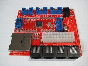
This board is the brains behind the Generation 3 Electronics. The heart is a Sanguino which is an Arduino-compatible board that is powered by an ATMEGA644P chip. It has connectors to hook up all the various peripherals that you'll need to drive a RepRap machine. It has headers for three stepper drivers, as well as 4 RJ45 connectors for Extruder Controller Boards. Not only that, but it has an SD card and a connector to hook it up to an ATX power supply.
Some highlights:
- Onboard atmega644p - 64K flash space, 4k ram, 32 I/O pins, Arduino compatible.
- 3 x Stepper driver connectors with min/max inputs.
- Built-in SD card socket for printing from file and buffering large print jobs.
- RS485 connection for noise-free communications with extruder / toolhead controllers.
- ATX power connector for power. It can also turn the power supply on and off.
- Headers to allow existing Sanguinos to plug straight in.
- I2C headers for simple hookup of external peripherals.
- On/Off switch for instant-kill and simple control of the entire system.
Hacks
See here in the Builder's Wiki for hacks to this board.
Get It!
Fully Assembled
- Coming soon!
Full Kit
Raw Components
Files
<div class="thumb tright"></div>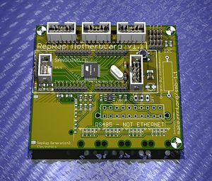
You can download the release file from SourceForge that has a bunch of helpful files for this board. It contains:
- GERBER files for getting it manufactured
- PDF files of the schematic, copper layers, and silkscreen
- Eagle source files for modification
- 3D rendered image as well as POVRay scene file
- exerciser code to test your board.
If you just want to peek at the files easily, check them out on Thingiverse.
Schematic
<div class="thumb tright"></div>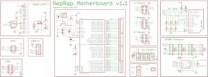
Interface
Pinout
Here is a handy reference that tells you what pins are hooked up to what features of the board.
<iframe width='600' height='720' frameborder='0' src='http://spreadsheets.google.com/pub?key=pmEMxYRcQzzCdmUPsPtJLbA&output=html&gid=3&single=true'></iframe>
Stepper Motor Headers
<div class="thumb tright"></div>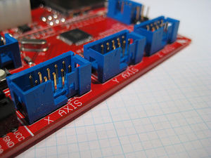
See our IDC cable construction page for info on how to make the IDC cables.
| Pin | Name | Function |
| 1 | N/C | Not Connected to anything |
| 2 | GND | Connect this to your uC to share a common ground. |
| 3 | Step | A pulse on this line will make the stepper motor advance one step in the desired direction. |
| 4 | Dir | If this pin is high, the motor will rotate forward, low it will rotate backwards. |
| 5 | Enable | This pin allows you to turn the motor on and off. The definitions of high/low are determined by your stepper driver. |
| 6 | Min | This is the signal from the 'min' sensor. The definitions of high/low are determined by your opto endstop. |
| 7 | Max | This is the signal from the 'max' sensor. The definitions of high/low are determined by your opto endstop. |
| 8 | GND | Connect this to uC to share a common ground. |
| 9 | GND | Connect this to uC to share a common ground. |
| 10 | GND | Connect this to uC to share a common ground. |
RS485 Comms + Power
<div class="thumb tright"></div>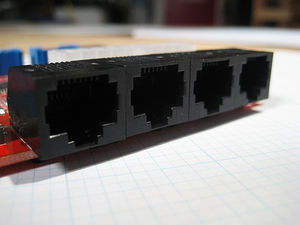
THIS IS NOT ETHERNET!
THIS IS NOT ETHERNET!
THIS IS NOT ETHERNET!
| Name | Function |
| 1 | RS485 A |
| 2 | RS485 B |
| 3 | +12V |
| 4 | +12V |
| 5 | +12V |
| 6 | GND |
| 7 | GND |
| 8 | GND |
This is one of the major new features of the Generation 3 electronics. RS485 is a robust serial communications channel. It uses differential signaling to provide very noise tolerant communications over relatively long distances, such as in a RepRap machine. RS485 is how the RepRap motherboard communicates with all the tool controllers. It is a very mature technology and is also pretty cheap. Definitely rad.
RS485 is a half-duplex channel, which means data can either be transmitted OR received at one time. This makes things a little bit tricky, but don't worry... we have it under control. What you need to know is that there are two wires that need to be hooked up: A and B. These are arbitrary names for the wires due to the differential signaling. Basically, you just have to make sure that all the A's and all the B's are wired up together.
To give a bit more insight into the way RS485 is implemented on the Extruder controller, we have given full control over the RS485 chip to the controller. It can independently enable or disable transmitting and receiving. One of the cool things about RS485 is that you can listen in to your own transmissions. This is a critical feature we exploit to ensure that we keep the transmit functionality enabled until all of our data has had a chance to be sent out.
Since RS485 only takes up 1 of the 4 pairs of wires in a Cat5e cable, we decided to use the rest of the pairs as power. This allows us to send something like 10 amps over the wire which is more than enough for most extruder needs. The extruder controller has an onboard voltage regulator to produce the 5v required for powering all the logic chips, as well as the optional servo motors. The H-bridges and MOSFETs are powered directly from this input voltage. The maximum allowable voltage is 18v to avoid overheating the 5v regulator.
Serial Header
<div class="thumb tright"></div>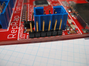
| Name | Color | Function |
| 1 | Black | GND |
| 2 | Brown | CTS# |
| 3 | Red | VCC |
| 4 | Orange | TXD |
| 5 | Yellow | RXD |
| 6 | Green | RTS# |
This is the serial communications header for programming and communicating with the board. It uses the same USB<->TTL header format as the Sanguino, Boarduino, or any of the other minimal Arduino clones. You can find out more information about the cable and where to get it on the Sanguino website. Its very easy to use.
I2C Headers
<div class="thumb tright"></div>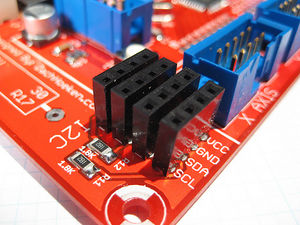
| PIN | FUNCTION |
| 1 | VCC (5v) |
| 2 | GND (0v) |
| 3 | SDA |
| 4 | SCL |
The extruder controller has left the I2C pins open for use as an I2C bus. This means you can use any number of really cool peripherals very easily! One idea is to use an I2C based LCD screen to print out information about the extruder for example.
The SDA and SCL pins even have built-in 4.7K pullup resistors to make configuration of the I2C bus hassle-free and automatic. The table below lists the pin-out of the header. The labeling in the v2.0 board is not too good, so pin 1 is towards the top of the board and in to the top and the right in the picture.
SD Card Slot
<div class="thumb tright"></div>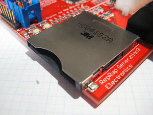
The RepRap motherboard can support SD cards up to 2GB. This means we'll be able to implement all sorts of awesome functionality like printing from card, full print job queueing, and many other awesome things that one can do with a 2GB non-volatile memory buffer. Get psyched.
ATX Power Supply Header
<div class="thumb tright"></div>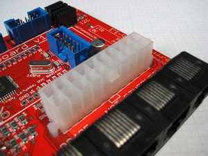
Just like a real computer motherboard, the RepRap motherboard has an ATX power supply header. Not only does this allow us to power the Motherboard easily and directly, but it gives us a little bit of control over the power supply itself. The ATX power supply provides a digital on/off switch that we have interfaced to the Motherboard. This allows us to turn the power supply itself on or off digitally. That gives the motherboard the power to simply and easily turn the entire system on or off in one fell swoop: extruders, stepper motors, everything. The power supply provides a standby 5V supply, so the Motherboard itself will still be powered even if the supply has been turned off.
Circuit Board
<div class="thumb tright"></div>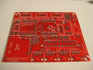
You can either buy this PCB from a supplier, or you can make your own. The image above shows the professionally manufactured PCB ready for soldering.
Components
<div class="thumb tright"></div>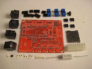
<iframe src="http://parts.reprap.org/embed/module/RepRap+Motherboard+v1.1" width="620" height="920" frameborder="0">Visit http://parts.reprap.org/embed/module/RepRap+Motherboard+v1.1</iframe>
Build Process
- You'll need a soldering toolkit to do most of this.
- You'll also need a SMT soldering toolkit to construct this board.
This board contains surface mount parts. Trust me when I tell you that it is really, really, really easy! The hardest part about SMT soldering is getting over your fear and staying calm. I've shown complete beginners how to do it, and they had no problems.
There are four parts to building a surface mount board using the Hotplate Reflow Technique:
- Apply solder paste to every exposed SMD pad
- Place each SMD component on its appropriate pad
- Place populated board on a cold hotplate. Turn hotplate on. Board solders itself!
- Solder in remaining through hole components.
1. Apply Solder Paste
<div class="thumb tright"></div>Okay, so this part is pretty easy: get your solder paste syringe and start applying solder paste to every SMD pad. I like to use a squeeze/tap method. That is, I squeeze a bit of solder paste out, then tap the place where it goes, rinse and repeat for every exposed pad. Do not put solder paste on pads with holes in them. You'll solder those in step #4.
2. Place Components
<div class="thumb tright"></div>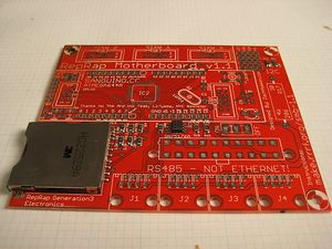
This is probably the trickiest part, but its not too bad once you get the hang of it. The nice thing is that if you mess up, you can reposition the component all day. You can even wipe off the solder paste and start over if you like. Very forgiving to the beginner. The individual components to place are shown below.
Its easiest with tweezers and some sort of magnification. A bit of patience and you'll get it no problem. Since nothing gets soldered yet, you can easily try and try again if you mess up.
R16 - 180 ohm resistor (181) - OPTIONAL
<div class="thumb tright"></div>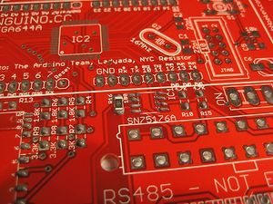
This component is optional, so I would suggest you leave it out. It is here for completeness. If you don't KNOW that you need it, leave it out.
R4, R5, R6, R11, R12 - 1.8K ohm resistor (182)
<div class="thumb tright"></div>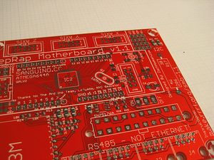
This component can be placed in any orientation.
R7, R8, R9 - 3.3K ohm resistor (332)
<div class="thumb tright"></div>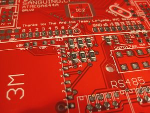
This component can be placed in any orientation.
R10, R15 - 4.7K ohm resistor (472)
<div class="thumb tright"></div>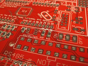
This component can be placed in any orientation.
R1, R13, R14 - 10K ohm resistor (1002)
<div class="thumb tright"></div>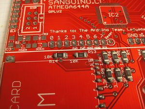
This component can be placed in any orientation.
C3, C5, C8 - 100nF ceramic capacitor
These components can be placed in any orientation.
R2, R3 - 1K ohm resistor (1001)
<div class="thumb tright"></div>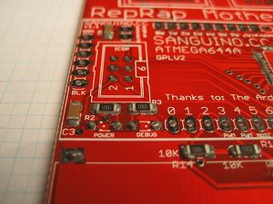
This component can be placed in any orientation.
Green and red LEDs
<div class="thumb tright"></div>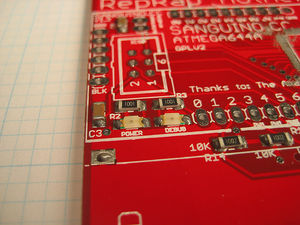
These components can not be placed in any orientation! The red and green LEDs must be oriented correctly. If you look very closely, you'll see that one end of each led has small green stripes along the edges. Position the LED so that these stripes are facing in the same direction as the white dot on the silkscreen. Zoom in on the picture to make sure you get them right!
C1, C2 - 15pF ceramic capacitor
<div class="thumb tright"></div>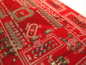
These components can be placed in any orientation.
C6 - 10uF electrolytic capacitor
<div class="thumb tright"></div>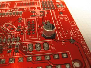
This component must be placed in the correct orientation. The black stripe on the capacitor should match up with the stripe on the silkscreen. Check the illustration to make sure you've got it right.
IC1 - SN75176A
<div class="thumb tright"></div>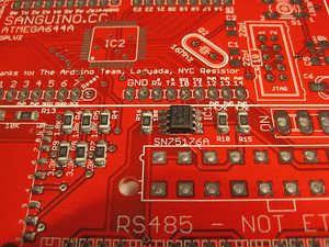
This is the RS485 communications chip. It must be placed in the proper orientation. Place the chip so that the line across one end of the chip matches up with the heavy line on the silkscreen. It should face the 'bottom' of the board.'
IC2 - Atmega644P TQFP
<div class="thumb tright"></div>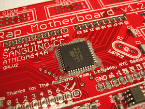
This is the microcontroller that is the heart of the Sanguino. Before you put down the chip, smear away the solder paste a little-- this helps reduce solder bridges. The small smooth circle on one corner of the chip lines up with the dot on the silkscreen. Check the picture above to ensure that you have the chip in the correct orientation. Make sure you get this right-- if you solder the chip in the wrong orientation, it will be almost impossible to desolder it!
SD Card Socket
<div class="thumb tright"></div>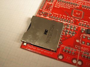
This one is really easy, and you can place it with your fingers even. If you look on the bottom of the SD card socket, you'll see two little nubs or 'bosses' that fit into corresponding holes on the PCB. When you line them up and place the SD card socket on the board, these will make sure that it goes in exactly the right spot. Nice.
Hot Plate Reflow
<div class="thumb tright"></div>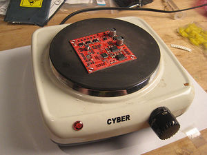
I prefer to start with the hotplate off. I burned a few boards one time by putting them on when it was already hot. Instead, carefully place the board on the cold hotplate, thn turn the heat up to a low temperature. Wait a few minutes for things to get cooking, and you'll see the small components begin to 'pop' as the solder goes molten. Keep an eye out for components that stick together. If that happens, simply nudge them apart with tweezers or other non-finger device. Wait until you see the largest component leads go silver (usually the big capacitors). If it starts to smell really bad, kill the power and solder the rest by hand. Sometimes the capacitors wont fully solder, so just hit the exposed pad with a soldering iron after the fact.
Once they have soldered, simply turn the hotplate off and let it cool down.
For detailed instructions on how to do hotplate reflow soldering, please see the Hotplate Reflow Technique guide.
Check for bridges!
Its important to check for potential bridging. It helps to have a magnifying glass, and backlighting. Just give it a thorough look-over. If you find bridges, they're easy to remove: Simply put some solder wick over the bridge, apply a hot iron over it, wait for the solder to wick up into the solder wick, then remove both. Double check the bridge. 90% of the time, enough solder will remain on the pins for a reliable connection. You may need to add a tiny bit of solder paste back onto the pin and re-solder it, but usually not.
Before
The second and third pins from the right are bridged:
<div class="thumb tright"></div>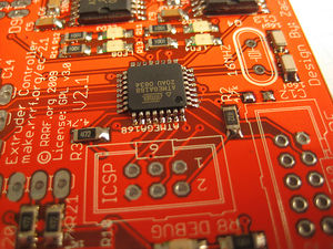
After
The second and third pins are separate! No extra solder needed:
<div class="thumb tright"></div>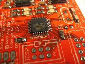
Check for Solder Balls
<div class="thumb tright"></div>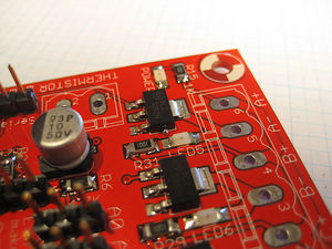
Sometimes if you use a bit too much solder, it will ball up and squeeze out the sides. These balls are fairly harmless, but you should definitely remove them with tweezers or even a small brush. Theres a chance that when they break free during use (and they will) that they will short something out, and you dont want that.
Solder Through Hole Components
16Mhz Crystal
<div class="thumb tright"></div>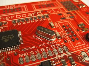
This can be inserted in any orientation. Make sure you trim the legs afterwards.
Reset Button
<div class="thumb tright"></div>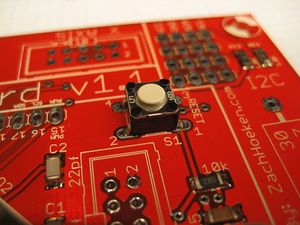
The button will snap into place. Solder it in and you're good.
On/Off - SPDT Switch
<div class="thumb tright"></div>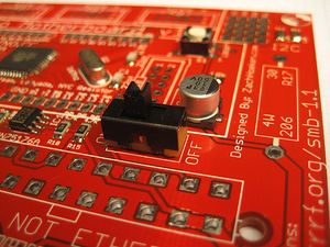
This is the on/off switch. You can insert it in any orientation. Push it all the way in and then solder it into place.
ICSP Header
<div class="thumb tright"></div>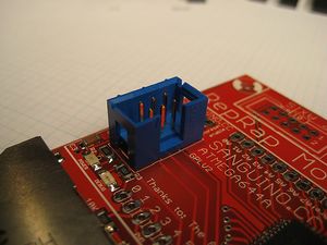
This is the ICSP header you'll need to burn the bootloader. Make sure you line up the notch with the notch on the silkscreen. It should be facing towards the inside of the board.
X/Y/Z Stepper Headers + JTAG
<div class="thumb tright"></div>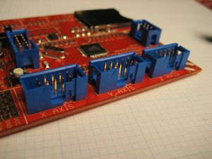
These are the headers where you plug the stepper drivers into. Make sure the opening on the IDC header faces outward (and lines up with the silkscreen). Don't forget the JTAG connector in the Sanguino area of the board.
6-pin serial header
<div class="thumb tright"></div>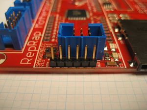
This is the header for the serial connection. You'll need to break off a set of 6 pins from the strip of pin headers included with the kit. Solder it into place.
ATX Motherboard Header
<div class="thumb tright"></div>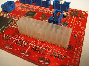
This is the header where you plug the ATX power supply into. There is a 'ramp' on one side with a corresponding rectangle on the silkscreen, and the part may also contain locking tabs that fit into the holes next to the silkscreen. Insert the part so that it lines up with these markings and then solder it into place.
RJ45 Connectors
<div class="thumb tright"></div>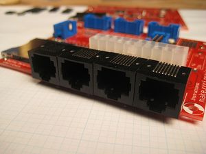
This is not ethernet.
We're re-using these jacks to provide power and comms to the Extruder controller using RS485. They can only be inserted one way and they snap into place. So snap them in and then solder them all up. Easy!
R17 - 30 ohm / 5W power resistor
<div class="thumb tright"></div>
This resistor is here basically to just suck power. Certain power supplies refuse to turn on unless there is a load on the 5V line. If you have one of those power supplies, then use the power resistor. Otherwise, feel free to leave it out. If you are not sure, then solder it in. It doesn't use much power in the grand scheme of things.
I2C - 4 pin female headers
<div class="thumb tright"></div>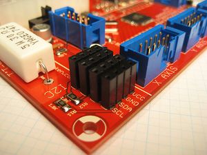
These are the headers for the I2C bus. They can be soldered in in any direction. Its easiest if you solder one leg on each one to tack them into place. Get a good grip and then re-heat the joint and push on the component until it is perfectly situated. Then you'll want to solder the rest of the leads.
10 pin female headers
<div class="thumb tright"></div>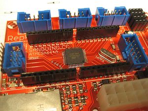
These headers give you direct access to the Sanguino pins should you need it. Pin headers do not come in 9-pin varieties, so you'll need to pull out one of the pins on a few of these to make them fit. This component is completely optional, but it doesn't hurt to solder it in.
Burn the Bootloader
<div class="thumb tright"></div>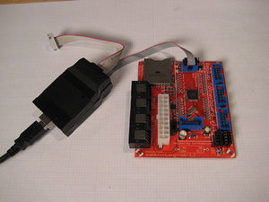
Before you start, make sure you have installed the Sanguino software modifications to Arduino.
The atmega644p chips come totally blank, so you'll need to upload the special program called a bootloader to the chip so that you can then easily program it with the Arduino software. In order to do this, you'll need an AVR programmer. I highly recommend the USBtinyISP from LadyAda. Its cheap, simple, and easy to assemble. It is also rock-solid. I've used it to program almost a thousand chips and it works great.
Before you start, make sure your extruder controller board is not hooked up to anything. In order to program the chip:
- Plug the USBtinyISP into your computers USB port
- Plug the USBtinyISP into the RepRap Motherboard.
- Open the Arduino software, make sure the 'Sanguino' option is selected in 'Boards', and then choose the menu option of "Tools -> Burn Bootloader -> w/ USBTinyISP".
Once you do that, a bunch of lights should start blinking and flashing. If everything is successful, then the Arduino software should tell you that it all went A-OK.
Program It!
There really isn't much to test on the board that it can do itself, so the easiest way to test it is to program the production firmware and to try using it.
Sanguino Master Firmware
There is a generic master firmware which allows the motherboard to control a RepRap machine. This firmware is part of the RepRap 3rd Generation protocol, which is described in greater deal on the RepRap 3rd Generation Firmware page. Go there for detailed instructions on how to install that software.
Wire it Up!
The Generation 3 electronics are mostly plug and play, so its really easy! Here are the main steps to hook up your RepRap Motherboard. These photos were taken on a CupCake CNC which has pre-cut holes to mount all the electronics nicely. However, if you have a RepRap it should be pretty simple to wire it up in a similar way.
Plug in ATX Power Supply
<div class="thumb tright"></div>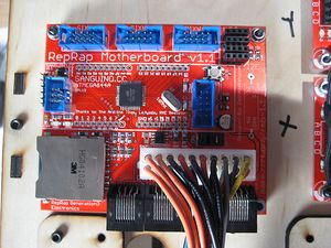
The first step is to plug the power supply into the motherboard. Make sure the power supply is off and unplugged before you do this step.
Plug in Stepper Drivers
<div class="thumb tright"></div>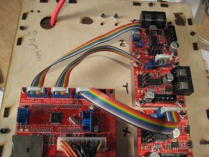
The stepper drivers are now connected with IDC cables. These cables are very easy to make and very easy to use. They have a little tab on them that only allows them to be inserted in one direction. Plug all of the stepper drivers into their appropriate headers (X/Y/Z). You're done!
Plug in Extruders / Toolheads
<div class="thumb tright"></div>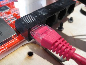
The RS485 power/comms bus is located on the bottom of the board. We are using standard Cat5e patch cables and RJ45 jacks. The board itself does not use ethernet, but we do use the same cables and connectors as ethernet. Please don't get confused and plug it into your router or internet. It is a multi-drop network with all devices wired in parallel, so simply plug the other end of your extruder into any open port. So easy, right?
Serial Communications
<div class="thumb tright"></div>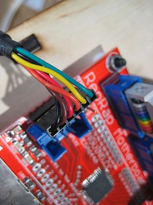
The communications to the host computer is done over a USB -> TTL serial connection. Simply plug the connector into the pin headers as shown and the other end into your USB port. Now you can talk to the motherboard. Rock.
History
Changelog
- Added ATX power supply header
- Added control over the atx power supply power sense pin.
- Combined RS485 and power into a single RJ45 jack connection.
- Switched to SMT version of the atmega644p.
- Various tweaks and polish to make the board nicer.
Previous Versions
- An upgrade to the previous RepRap Motherboard v1.0