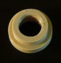
Mini J Head Nozzle
Release status: working
| Description | Mini J-Head Nozzle, Thermal Barrier, and Mounting Plate based on the J Head Nozzle.
|
| License | GPL
|
| Author | |
| Contributors | |
| Based-on | |
| Categories | |
| CAD Models | |
| External Link |
Introduction
Note: With the development of a 1.75mm conversion, for the J-Head Nozzle, the Mini J-Head Nozzle has not been made in any quantity.
Originally, the Mk I had been designed as a drop-in replacement for the RepRap Universal Mini Extruder hot end that utilized 1.75mm filament. Afterwards, this hot-end design was abandoned. However, due to the demand for a 1.75mm J-head hot-end, the Mk II has been developed.
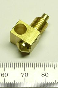
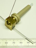
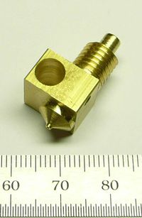
The Mini J-Head Mk II is identical, externally, to the J-Head Mk V. However, internally, both the brass nozzle/heater and PEEK nozzle holder are designed specifically for the 1.75mm filament and a 4mm OD/2mm ID PTFE liner.
Advantages
- Internally, the filament path is identical to that of an already proven design.
- The design is simple as the number of custom machined parts is kept to a minimum.
- If necessary, the PTFE liner can be replaced by using an off-the-shelf piece of PTFE tubing.
- The PTFE is not stressed nor used to provide support. This reduces a point of failure that is part of other designs.
- A resistor is used as a heater. There is no need to wrap nichrome wire or to bake a heater core.
- Heat transmission is improved as there is no thermal junction where a separate heater screws onto the nozzle.
- With most versions weighing in at under 25 grams, this design is very light.
Disadvantages
- Considerable machining is required.
Parts List
Mk I
| Quantity | Part | Description | Part Number |
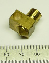
| 1 | Mini J-Head Nozzle (v1) | Machined Brass Nozzle/Heater Combination, Version 1 | |
| 1 | Thermal Barrier | Machined PEEK Insulator | |
| 1 | Mounting Plate Insulator | Machined Internally Threaded PEEK Insulator | |
| 1 | Mounting Plate | Machined Rectangular Aluminum Mounting Plate | |
| 1 | PTFE Liner | 4mm OD, 2mm ID PTFE Tubing | McMaster-Carr 52335K32 |
| 1 | Heater Resistor | Axial, 5.6 ohm, 1%, 5W | UB5C-5.6-ND |
| 1 | Thermistor | 100K | B57560G104F |
Mk II
| Quantity | Part | Description | Part Number |
| 1 | Mini J-Head Nozzle (v2) | Machined Brass Nozzle/Heater Combination, Version 2 | |
| 1 | Nozzle Holder (v1) | Machined PEEK Nozzle Holder, Version 1 | |
| 1 | PTFE Liner | 4mm OD, 2mm ID PTFE Tubing | McMaster-Carr 52335K32 |
| 1 | Heater Resistor | Axial, 5.6 ohm, 1%, 5W | UB5C-5.6-ND |
| 1 | Thermistor | 100K | B57560G104F |
Sundries
| Description | Part Number |
| PTFE Insulation For Thermistor, 0.012" ID | McMaster-Carr 5335K9 |
| PTFE Insulation For Heater Resistor, 0.047" ID | McMaster-Carr 5335K15 |
| 20 AWG High Temperature Wire | McMaster-Carr 8209K11 |
Machined Parts
Mini J-Head Nozzle
Version 1
Material: Brass Bar Stock, 5/8" Square Or 5/8" x 1/2" Rectangular, 0.875 Long
Note: The machining process can vary depending upon available machinery and tooling. The minimum machining requirements are a metal lathe with a 4-jaw independent chuck.
- Cut a piece of brass bar stock 0.875 long plus enough to adequately hold the stock in the lathe.
- On the brass bar stock, find the center of the axis of the nozzle. This can be done by various means ranging from using a milling machine to using marking fluid, a height gauge, and a surface plate.
- Mount the brass bar stock in a 4-jaw chuck on a lathe. Adjust the chuck so that the nozzle axis is on center.
- Turn the threaded end of the nozzle down to 0.375 +0.000 -0.004. The threaded end will be 0.375, from the top end to the heater block section.
- Cut a relief groove to an OD of 0.305. This closest edge, of this groove, will be 0.100 from the heater block section. While the groove is about 0.040 wide, it's width is not critical.
- Thread the nozzle to 3/8-24 up to the relief groove created in the proceeding step.
- Using a 6mm drill bit, drill out the center of the nozzle to a depth of 0.375.
- Using a 4mm drill bit, drill out the center of the nozzle to a depth of 0.725.
- Remove the work piece and mount it by the threaded end so that the threaded end is centered in the lathe.
- Cut-off any excess material.
- Machine the nozzle tip to the desired profile. Leave the heater block section 0.325 thick.
- Drill the nozzle orifice.
- Mill or turn off the excess material in the heater section. This can be accomplished by mounting the nozzle in the 4-jaw chuck sideways so that the excess material is presented for machining. If available, a milling machine can also be used. (If a 5/8" x 1/2" piece of bar stock is used, this step will be skipped.)
- Using a letter size A drill bit, drill out the hole for the heater resistor.
- Drill out the hole for the thermistor.
Version 2
Material: Brass Bar Stock, 1/2" Square, 1" Long
Finished Weight: Unknown
- Cut a piece of brass bar stock 1 inch long plus enough to adequately hold the stock in the lathe.
- On the brass bar stock, find the center of the axis of the nozzle. This can be done by various means ranging from using a milling machine to using marking fluid, a height gauge, and a surface plate.
- Mount the brass bar stock in a 4-jaw chuck on a lathe. Adjust the chuck so that the nozzle axis is on center.
- Turn the threaded end of the nozzle down to 0.3125 +0.000 -0.004. This section is 0.500 +-0.005 long.
- For the first 0.150 +-0.010, of the threaded section, down to an OD of 0.157 (4mm) +0.000 -0.002.
- Thread the nozzle to 5/16-24 up to the shoulder of the heater section.
- Drill out the center of the nozzle with a 2mm drill bit. This will create a heat chamber that is the entire length of the brass nozzle.
- Remove the work piece and mount it by the threaded end so that the threaded end is centered in the lathe.
- Cut-off any excess material.
- Machine the nozzle tip to the desired profile leaving the heater block section 0.325 thick.
- Drill the nozzle orifice.
- Using a size A drill bit, drill the heater resistor hole through the heater block section.
- Drill the thermistor hole.
Nozzle Holder
Version 1
Material: PEEK, 5/8" Round, 40mm Long
Finished Weight: ??
- Cut a piece of 5/8" round PEEK to length
- Drill out the center of the PEEK using a 4.2mm drill bit.
- Using a letter size I drill bit, enlarge one end to a depth of 0.450 +-0.010.
- Drill out 0.125 +-0.005, from this end, to an ID of 0.320 +-0.005.
- Internally thread the end to 5/16-24 using a bottom tap.
- Taper the hot-end such that there is a 30 degree taper that starts at 5mm from the axis of the nozzle and tapers outwards to the OD. Optionally, a shoulder could be cut in place of a taper. The purpose of this taper is to reduce the amount of contact the PEEK has with the brass.
- Using a number 7 drill bit, drill out the cold end for a distance of 0.250.
- Internally thread the cold end to 1/4-20.
- Optional: 4.76mm from the cold end, turn a groove that is 4.64mm wide with a root of 12mm.
- Optional: At the hot end of the nozzle holder, mill two flats opposite of each-other for using a 1/2" (13mm) open end wrench. Each flat will be 0.250 (6.5mm) wide and 0.250 (6.5mm) from the axis of the nozzle holder.
- Mount the nozzle holder in an indexer on a milling machine.
- Equip the milling machine with a 2mm or 3/32 end mill. (The dimensions of the end mill do not have to be very precise.)
- Start the first groove so that it's edge is 0.500" from the hot-end of the nozzle holder.
- Mill 5 grooves as follows. The grooves will be interrupted for the supports.
- Each groove is 0.150" deep.
- The centers, of each groove, are 0.125" apart.
- Each groove has an angular cut of 90 degrees and is milled between the following angles: 0-90, 120-210, 240-330
- Each groove support is drilled out at the following angles with the center, of it's support, at 90 degrees to the end mill: 15, 135, 255
- To drill out each groove support, the end-mill is positioned so that it's edge, towards the center of the nozzle holder, is 0.150" from the outer edge of the nozzle holder.
Thermal Barrier
Material: PEEK, 8mm Round, 0.775 Long
- Drill out the ID to 4mm.
- Turn down the end, that will be the closest to the hot end, to an OD of 6mm for a distance of 0.425.
- Cut a 30 degree taper on the tip of the hot end of the thermal barrier.
PTFE Liner
Material: PTFE tubing, 4mm OD, 2mm ID, 2 1/2 inches long
- Using a razor knife, cut the tubing to length.
- Cut an approximately 30 degree (or greater) taper on what will be the hot-end of the PTFE liner.
- After assembly, cut the tubing to fit the application.
Mounting Plate Insulator
Material: PEEK, 5/8" Round, 0.250 Long
- Cut a piece of PEEK to length plus enough to mount in the lathe.
- Turn down the shoulder to an OD of 0.500 -0.000 +0.0510. The shoulder will take up 1/2 the length of the PEEK insulator or about 0.125.
- Using a letter size Q drill bit, drill out the ID.
- Internally thread to 3/8-24.
- Cut off the mounting plate insulator so that it is about 0.250 long.
Mounting Plate
Material: Aluminum, 3/4 inch wide x 1/8 inch thick, 34mm Long
- Cut the mounting plate to the above dimensions.
- In the center (17mm from one end and 3/8 inch from the side) of the plate, drill a 1/2 inch hole.
- Drill both 3mm holes centered (3/8 inch from the side) 3mm from each end.
Assembly
Mk I

- Hold the nozzle so that the threads are up.
- Install the Mounting Plate.
- Screw on the Mounting Plate Insulator so that the shoulder is towards the mounting plate.
- Push the Thermal Barrier into the nozzle.
- Slide the PTFE Liner into the Thermal Barrier so that the tapered end goes into the nozzle.
Mk II
Notes
General
Testing
Mk I
It is unknown whether the Mk I was ever tested.
Mk II
- PLA has been successfully printed at 183mm/sec.
- No jams or leaks have been reported.
