LulzBot/Prusa Mendel
Release status: working

| Description | LulzBot Prusa Mendel is a lightly tweaked version of the Prusa Mendel Prusa_Mendel.
|
| License | |
| Author | |
| Contributors | |
| Based-on | |
| Categories | |
| CAD Models | |
| External Link |

Contents
Intro
The LulzBot Prusa Mendel build is a lightly tweaked version of the Prusa Mendel RepRap printer. There are only a few tweaked parts and settings in the build. Listed below are all of the changes or additions including parts and hardware. Also listed are instructions for completing the build that differ from the Prusa Mendel instructions.
Changes
Here is a working list of the changes you will find that differ from the Prusa Mendel. The current sets include a few parts from the cast Clonedel Prusa Mendel build parts
- 2 cast Vertices and 4 cast Vertices with feet
X-axis
- X-ends
- Cast X-end-idler and X-end-motor
- Printable X-end-clamp
- Hardware changes and additions
- x8 M3 25mm SHCS, replaces x8 M3x10 bolts in the Prusa build
- x8 M3 Nyloc nuts
- x16 M3 Washers
- x2 M8 nut
- Supa-Flat X-carriage
- x4 Boltable PLA bushings for the X-carriage
- Extra hardware needed in place of using glue to attach the bushings
- x8 M3 10mm SHCS
- x8 M3 nut
Extruder
- Modified wade extruder
- This part is built and installed exactly the same as the regular Wade's extruder. The changes in the design are for easier printing and longer motor mount spaces to allow the motor to be pushed over to loosen or tighten the extruder mount screw.
Y-axis
- x4 Boltable PLA bushings for the Y-axis bed
- Extra hardware is needed to mount the Boltable PLA bushing to your bed platform. You're going to need 8 M3 Screws and nuts, and 16 M3 washers. The length of the screws will depend on the thickness and type of mount plate you use.
- For the Lulzbot Aluminum bed mount plate you will only need x8 M3 10mm SHCS for the bushings, x4 M3 16mm SHCS for the belt clamps, and x12 M3 washers. The plate has tapped holes so nuts are not needed.
Additions
- For use with the Lulzbot Aluminum bed mount plate, 2 belt stand-offs are included.
- Printed opto-flags for the Y and Z axes
- Endstop holders have added stand-offs
- x2 12 toothed pulleys as an optional update from the standard 8 tooth pulley
Instructions
The assembly instructions for the Prusa Mendel can be followed for the printer build besides the following changes:
Y-Axis
This is the trickiest change, as the instructions depend on the bed platform you use. If you use the normal Prusa Mendel thick sheet bottom and top plate than the only change for the y-axis is that the 4 bushings are screwed onto the bottom plate rather than glued.
If you are using the Lulzbot Aluminum bed mount plate follow these instructions when installing the y-axis:
- Install the 4 mountable bushings onto the mount plate using the 8 M3 10mm screws and washers. Also install the belt stand-offs (fig. 3.1.1) and clamps with the 4 M3 16mm screws and washers (leave the belt clamps loose for now).
- Slide the two 406mm smooth rods into the bushings you've just installed. Make sure the rods slide smooth; if not, you need to further ream the bushings. Also, check to make sure your rods are running parallel. If not adjust the mounted bushings and re-tighten them.
- Now for the major difference from the Prusa instructions: The Y-axis smooth rods are installed above the front and rear threaded rods. The bar clamps should be upside down compared to the Prusa instructions. See figure 3.1.2
- Continue following the Prusa instructions on aligning and squaring the bed. Check that you have smooth movement.
- When installing the y-axis belt, note that the belt is installed under the bed mount plate (fig. 3.1.3)
3.1.1 Belt stand-off and clamp
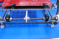
3.1.2 Y axis smooth rod installation
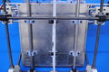
3.1.3 Y axis belt configuration


X-Axis
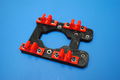
X-carriage
- First set all of the nuts into the Supa-Flat X-carriage. You should be setting 12 M3 nuts and 2 M4 nuts. We thermal set the nuts in our printers using a soldering iron (fig. 3.2.1.1). The nuts heat up and slides into the nut traps. This leaves the nuts snug and stops them from falling out.
- Now install the 4 bushings using 8 M3 10mm screws and 8 M3 washers (fig. 3.2.1.2). Also install the two belt clamps, but again leave them loose.
- Slide the two 420mm smooth rods into the carriage bushings and check that they are parallel and move smooth. Ream and adjust the bushing accordingly.
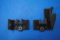
X-ends
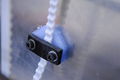
- Thermally set one M8 nut into the x-end-idler (fig. 3.2.2.1)
- Place one x-end-clamp on to the x-end-idler. The x-end-clamp should be above the x-end-idler.
- Using 4 M3 25mm socket screws (with one M3 washer on each screw), push them through the bottom holes of the x-end-idler through the top of the x-end-clamp.
- Put one M3 washer on each screw against the top of the x-end-clamp. Put an M3 Nyloc nut on each screw and tighten them down a bit, but leave the clamps a little loose.
- Repeat these steps for the x-end-motor-mount
- The rest of the x-axis installation is the same including gluing 2 PLA bushings on each x-end. Once you have the smooth rods slid into the x-ends, tighten down the 8 Nyloc nuts.
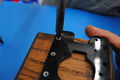
3.2.1.1 Thermal setting nuts
3.2.1.2 Supa-Flat carriage with bushings
3.2.2.1 Thermally set M8 nuts in X-ends


