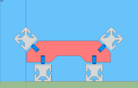
Betzbot
Release status: experimental
| Description | Gada Prize Entry
|
| License | |
| Author | |
| Contributors | |
| Based-on | [[]]
|
| Categories | |
| CAD Models | |
| External Link |
Contents
Name
The Betzbot is named after Vladimir Betz, a Russian anatomist and histologist famous for the discovery of giant pyramidal neurons of primary motor cortex.
Design Criteria
Primary Design Criteria
- Print with at least three different materials*
- Print electrically conductive material
- Print Electronic Circuit Boards*
- Print Bed usable through 20 print cycles*
- Total cost, not including Print Bed, not exceeding $200*
- Not less than 90% of the volume of the printer must be printed*
- Build volume of at least 300x300x100mm
- Full part set printable in under 10 days unassisted save cleaning one head jam
- Print untethered from PC
- Consume no more than 60 watts*
- *Clarification Needed
T-slot Construction
Betzbot is designed to be built using Plastic T-slot gained through printing or die extrusion. The variety of T-slot accessories available as well as it's availability in the more expensive, more rigid, aluminum will allow for different configurations to be tested and lend easy to modification and personalization. The profile in design for Betzbot is currently available on thingiverse at thing:9013.
Axis & Frame
Many different configurations exits, each with their own set of advantages and disadvantages.
| Example | X-Axis | Y-Axis | Z-Axis | Pro | Con |
|---|---|---|---|---|---|
| Mendel | Toolhead | Bed | Carries X | ||
| Thing-O-Matic | Bed | Carries X | Toolhead | ||
| Ultimaker | Toolhead, Y | Toolhead, X | Bed | ||
| MicRo | Carries Z | Carries X | Toolhead |
The limiting design constraint for this aspect of the machine is the rigid frame and precise axis constraint. It is likely several configurations will be designed, built and tested to determine which is most suitable.
Smooth Rail, Rack & Pinion
Betzbot uses a printed smooth rail for axis constraint. By printing on the diagonal against a smooth flat surface it is possible to print a rigid, smooth rail up to <math>\sqrt{2} </math> of your bed length minus the width of the rail. The flatness and smoothness are determined by the properties of the bed, since the surface used is the one that was printed against the bed. The current design uses a smooth rail attached to plastic 20mm T-slot. Multiple Rails are used for full axis constraint.
The following instructions presume equal bed width and length. Units are in mm.
- Extrude the rail so that the length is almost but less than (1.41*Bed length - 25)
- Disable Outline in your slicing software
- Start printing a single layer and adjust the models location to fit snuggly against your printable corners
- Lay down 20mm wide or greater kapton tape along the diagonal where your model will be printed
- Print and allow to cool - Do NOT remove from bed
- While on the print bed, bolt the rail to a 20mm T-slot extrusion
- Using the small gaps along the sides of the print, gently pop the rail of the print bed
Toolheads
Peristaltic Paste Extruders
The paste extruders will extrude viscous one part epoxy compounds, one conductive, and one insulative.
Thermoplastic Extruders
One or more thermoplastic extruders will be used.
Project Log
June 5, 2011
- Added the bulk of the initial content to the wiki.
June 3, 2011
- 20mm Plastic T-Slot Extrusion released as a prototype on Thingiverse.
May 27, 2011
- Second major group brainstorming session.
- Name chosen for Gada entry project.
- Some printing tests completed for slotted rail, more tests to come.
- Conductive epoxy source and information located.
- Method for printed hotend drafted
- Method for printed PCB's drafted
May 17, 2011
- Initial group brainstorming session. User:Alex Alex English joins the team which originally consisted of Luke Chilson.
- Decision to pursue slotted rail printing tests.


