Generation 1 Electronics
Contents
Generation 1 Electronics
Once you start putting electricity into your RepRap - even at just 12 volts - you have to take basic, common sense precautions to avoid fires. Just in case these fail, test your workshop smoke detector. Got no smoke detector? Get one!
Wires and Connectors
Electronics are no good on their own, they need to be connected together in order to do something really useful. Obviously you're going to want to use some sort of wire, but which one and how will you connect it?? Dont worry, because in this guide we will attempt to simplify it for you.
Power Supply
The RepRap machine needs a regulated power supply giving at least 8 amps at 12 volts. The easiest way to do this is to convert a normal PC power supply into a RepRap power supply.
PowerComms Card v1.3
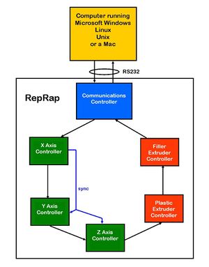
The Power / Communications card is the link between the computer and the RepRap printer. It uses RS232 to communicate over a serial port. If you do not have access to a serial port on your computer, there are widely available USB -> RS232 converters available. It also distributes the 12v power via connectors for all the other boards.
Signals are passed from the RS232 around the communications ring until they arrive at the device to which they are addressed, which then acts upon them. Thus the RS232 Transmit from the Communications board goes to the Receive on the first controller; that board's Transmit goes to the next board's Receive, and so on, just like the diagram on the right.
There is an extra single-wire synchronization link from the X axis controller to the other two axes. This allows all the steppers to move together in any straight line without their needing to transmit data round the ring for each step.
Stepper Tester v1.0 (optional)
This tiny little board can be plugged in where the stepper motor (or extruder motor) would normally go. It has 4 LED's to tell you exactly what is going on with your motor output. Useful for debugging and determining what exactly is going wrong, if something is going wrong.
Stepper Motors
Darwin's powerhouse. You'll need three of these. Note that the X-axis is wired differently to the other two.
PIC in-circuit programming
You can program the PIC chips that the following boards use by putting them in a programmer, but it is also possible to program them in circuit. This saves the bother and pin-bending of taking them in and out of the circuit boards. See how here.
Stepper Controller Card v1.2
Each stepper controller card drives one of the stepper motors. You need three of these boards for a fully functioning RepRap. Each board controls the position of one axis. Together, they position the print head anywhere in the 3 dimensional build area.
Opto Endstop v1.0
Darwin's Cartesian axes all need a datum (also known as home position or end-stop) to reference their movements. At the start of each build each axis needs to back up until the datum point is reached. For Darwin, we use one opto-switch for each axis to define its position. This page tells you how to wire one up to a bracket used in Darwin's design.
Extruder Controller Card v1.2
The extruder controller card drives an extruder (print head). You need two of these boards for a fully-functioning RepRap. Each board controls one print head. The board controls the temperature and heating coils needed to melt the plastic. It also powers and runs a motor that feeds plastic into the extruder which is then melted and extruded. One board controls the printing of the plastic that forms the object being built; the other controls the extrusion of a disposable support material for where there are overhangs. Together, these extruders physically do the printing of the objects being made.
