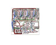
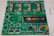
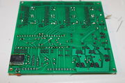
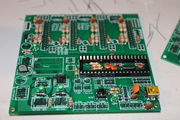
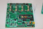
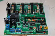
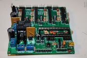
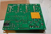
Build Sanguish1.1
Release status: working
| Description | All in one electronics with Toshiba drivers
|
| License | [GPL]
|
| Author | |
| Contributors | |
| Based-on | |
| Categories | |
| CAD Models | |
| External Link | (none)
|
Sanguish ----- Build Sanguish1.0 ----- Build Sanguish1.1 ----- Firmware for Sanguish ----- Use Sanguish
Contents
Assembly Instructions
You will first need to decide what voltage you will run your heaters and motors at. The motors and heaters can be powered from different voltages. Then decide what your max current will be for each stepper driver. Most commonly all the drivers will be set the same, but if you are going to run your Z axis with two motors in parallel then you may want the Z driver to have double the max current. Max current depends on the motors. Often motors are run at some fraction of their max rated current. This will give less torque but will allow the motors to run cooler. One easy option would be to set the max current equal to the motor max rated current, and then you could set the torque jumpers to 75% if they run too hot. These drivers don't have a potentiometer to set max current so you are limited to four settings. Once you set the max current via the current sense resistors, you get only 100%, 75%, 50%, and 20% current via the torque jumpers. If you leave one of the current sense resistor sockets empty it would be fairly easy to increase the max current later by soldering additional resistors into the empty spots.
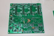
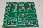
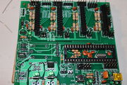
There are two resistors per coil and two coils per driver. The two resistors for each coil are wired in parallel, so the current from each simply adds together. Included in the kit are three different resistors. 0.5 ohm (green black silver gold) = 1 amp 1 ohm (brown black gold gold) = 0.5 amp 1.5 ohm (brown green gold gold) = 0.33 amp The two resistors indicated are both for the first coil of the first stepper. The two below are for the other coil. The pictured board is set to 2 amps max current for all coils. 0.5 ohm + 1 ohm would give 1.5 amps max. 1.5 ohm + 1 ohm would give .83 amps max. Set both coils of the same driver the same. Separate drivers can be different.
Possible combinations using resistors supplied in the kit would be:
one 1.5 ohm resistor per coil = 0.33 amp max
one 1 ohm resistor per coil = 0.5 amp max
1.5 ohm and 1 ohm resistors per coil = 0.83 amp max
one 0.5 ohm resistor per coil = 1 amp max
1.5 ohm and 0.5 ohm resistors per coil = 1.33 amp max
1.0 ohm and 0.5 ohm resistors per coil = 1.5 amp max
two 0.5 ohm resistors per coil = 2 amp max
For other resistors not supplied in the kit the equation for current is I=0.5/R where R is the resistance and I is the current.
Electronic Components
| Description | Part Number | Quantity | Comments
|
|---|---|---|---|
| 360 Ohm resistor | R11, R12, R34, R42 | 5 | LED and Transistor bias. Optional R66 for 24V conversion. |
| Wire Jumper for relay coil | R66 | 5 | For 12V driver power. Use 360 Ohm for 24V supply. |
| 4.7 K Ohm resistor | RT1, RT2 | 2 | Thermistor voltage divider |
| 2.2 K Ohm resistor | R14, R22, R30, R69, R70 | 5 | 12V LED current limiting, and weak pull ups. |
| 0.5 Ohm 1/2 W resistor | R50-R65 | 16 | Current sense resistors. As desired for your max current. |
| 1 Ohm 1/4 W resistor | R50-R65 | 8 | Current sense resistors. As desired for your max current. |
| 1.5 Ohm 1/4 W resistor | R50-R65 | 8 | Current sense resistors. As desired for your max current. |
| Diodes | D1-D3 | 3 | Protection diodes for FET's and 7805. |
| 40 pin female header | 0 | 3 | Sockets for driver chips |
| single row 40 pin male header | 0 | 1.5 | jumper headers, connectors etc. |
| dual row 40 pin male header | 0 | 1 | jumper headers, connectors etc. |
| 10 A Relay | Relay1 | 1 | Power on sequencing switch |
| 40 Pin Dip socket | U1 | 1 | Socket for Atmega |
| ATMega | U1 | 1 | 644P or 1284P |
| Crystal | U6 | 1 | 16 or 20 MHz |
| 22 pf Capacitor | C3, C4 | 2 | for crystal oscillator |
| NO Push button switch | Reset | 1 | Reset Switch |
| 0.1 uf ceramic capacitor | C5, C14-19, C24-27, C29 | 13 | various |
| 33 uf electrolytic capacitor | CT1, CT2, CT10-CT13 | 6 | driver isolation and temp |
| 330 uf electrolytic capacitor | C1, C7 | 2 | Motor and heater power input caps |
| Toshiba TB6560AHQ drivers | U10-U13 | 4 | stepper drivers |
| Small power FET | Q2, Q5 | 2 | Hot end and relay driver |
| Large power FET | Q1 | 1 | Heated Bed |
| LED | LED2, LED5, LED6, LED9 | 4 | heater indicators, power indicators |
| 2 pos screw terminal | Power1, Power2, Heater1, Heater2 | 4 | power in and heater out |
| 100 pf ceramic capacitor | C20, C21, C22, C23 | 4 | driver clock capacitors |
Photos of Assembly
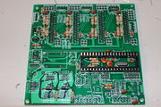
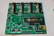
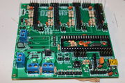
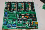
Here is a brief pictorial with instructions. You can click on each picture to get a larger view. Component markings are indicated in parenthesis like this (red, red, brown)
Adjusting for higher voltage inputs
Motor and Heater power inputs are independent and can be powered differently.
If you decide to power the motors with voltages higher than 12V you must use a current limiting resistor on R66 to adjust the current to the relay coil. A spare 360 ohm resistor is included for adjusting the current for 24V. In addition you should probably add a heat sink to the 7805 voltage regulator. Max voltage to the motor drivers is 36V so 24 to 28 V is probably a good working maximum.
For the heater power most heated beds and hot ends are designed for 12V. Higher voltages are not recommended for 12V heaters. If your heaters are designed for higher voltages then you may use a higher voltage up to 24V without changes to the board.
Testing
Before powering the board check both power input terminals for shorts. Resistance across the +/- screws of Power1 and Power 2 should be high. I get in the 200 kOhm range on Power 1 (Motor power input) and about 5 MegaOhm on Power 2 (heater power input)
Also check the 5V supply for shorts. I get about 3 kOhm from 5V to ground.
The exact measurements are not essential but if you get in the low tens or hundreds of Ohms on any of the measurements you should check for solder bridges before applying power.
