VerticalPlatform
The RepRap Vertical Axis
Version 1
1. Summary
This describes how to construct the vertical axis of a prototype RepRap from FDM'd parts. As with other RepRap components, this axis and platform was designed to be made by the RepRap rapid prototyper itself, and thus consists of standard parts plus rapid-prototyped components. Very few modifications are required to the standard components.
The platform is designed to be raised and lowered to an accuracy of better than 0.1mm by means of a stepper motor and threaded rods. The whole is designed to be mounted on a carriage on the linear axis, and to transport either a second linear axis or a turntable assembly.
2. Introduction
The axis is derrived from an experimental Meccano axis, used to produce parts from EVA during the early stages of RepRap development. This prototype worked, but was prone to uneven descent of the platform as it used only one screw to raise and lower it. Although 3 guide rails were used, these had a tendency to bind at awkward moments, resulting in a see-saw motion during descent.
As the platform is mostly used after a period of descent, and the margin of error is relatively large compared with the amount of each unit of descent, there is no current need for anti-backlash gearing.
The first FDM'd prototype uses 3 pieces of M5 studding to control the descent of the platform, which adds greater stability. These pieces of studding are turned by 3 large gears, which in turn are driven by a stepper motor (see this section for intricate design details]. The gearing provides approximately 5:1 reduction of a 7.5 degree stepper motor, rotating the studding in 1.5 degree steps. The thread pitch on M5 studding from this table http://www.hydra.co.za/technical/thread.pdf is 0.8mm, resulting in a theoretical 30 steps to move the platform by 0.1mm vertically. This overkill is needed because of the gearing ratio required to allow the stepper motor's torque to lift the platform assembly under load.
Identical end pieces are used at the top and bottom of the lengths of studding, which as well as holding bearings for the studding form anchor points for the stepper motor and equipment attached to the top of the platform.
Provision has been made for additional stiffening should it be required. The studding runs through captive nuts mounted on the carriage of a linear axis, causing the whole platform assembly to raise and lower when the stepper motor turns.
To Be Continued...
Licence
RepRap is copyright 2005 University of Bath, the RepRap researchers (see the project's People page), and other contributors.
This web page and all the other files in its download are covered by that copyright.
Principal author:
Adrian Bowyer Department of Mechanical Engineering Faculty of Engineering and Design University of Bath Bath BA2 7AY U.K. e-mail: [email protected]
RepRap is free; you can redistribute it and/or modify it under the terms of the GNU Library General Public Licence as published by the Free Software Foundation; either version 2 of the Licence, or (at your option) any later version.
RepRap is distributed in the hope that it will be useful, but WITHOUT ANY WARRANTY; without even the implied warranty of MERCHANTABILITY or FITNESS FOR A PARTICULAR PURPOSE. See the GNU Library General Public Licence for more details.
For this purpose the words "software" and "library" in the GNU Library General Public Licence are taken to mean any and all computer programs computer files data results documents and other copyright information available from the RepRap project.
You should have received a copy of the GNU Library General Public Licence along with RepRap; if not, write to the Free Software Foundation, Inc., 675 Mass Ave, Cambridge, MA 02139, USA, or see
http://www.gnu.org/
-- Main.VikOlliver - 25 Nov 2005
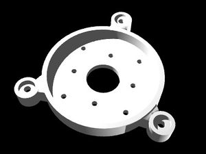
- [[File:VerticalPlatform-lower spider2.aoi: Second version of the spider used to hold the vertical axis gears|thumb]]
- AoI Rendering of the spider designed to hold the gears:
- [[turntable_vertical_cogs.aoi: AoI file of gears used in vertical platform.|thumb]]
