ThermoplastExtruder
This page describes something which is no longer the most recent version. For the replacement version see: RepRapOneDarwinThermoplastExtruder
This document describes the Version 2 RepRap polymorph / thermoplast extruder head. It is intended to allow other researchers to reproduce the results. The head was designed to be made by the RepRap rapid prototyper itself, and thus consists of standard parts plus rapid-prototyped components. There were also a few parts that required other tools to make; the intent of the design was to make these parts as simple as possible, to minimise the tools needed, and to keep their number as small as possible. The head extruded a stream of Polymorph polymer about 0.5 mm in diameter at a temperature of 140 oC and a rate of up to 4 mms-1. The extruder is experimental, in that many parameters for it (particularly in the software) are user-set and controlled, whereas in a finished RepRap machine these would permenantly be set to defaults.
Contents
Introduction
My Version 1 RepRap polymorph extruder head has the great virtue that it works, but it also has some shortcomings. The main ones are that it is quite expensive to make, that it has a lot of moving parts, and that some of the components are rather hard to obtain.
Consequently I decided to revisit an idea of Vik Olliver's that he blogged on 14 June 2005. Here is his original sketch:
This is so neat that I attempted to make such a design before I made the Version 1 Extruder, but it didn't work. The problems were twofold:
- The resistance of the heated nozzle extruder (which would be just below the bottom of Vik's drawing) was too great, and
- The screw tended to chew up the polymorph rod, a problem from which the device couldn't recover.
However, when I made Version 1, I discovered that keeping the polymorph fine-nozzle very short reduced flow resistance dramatically. So I thought that maybe, with that new nozzle, Vik's idea could be made to go.
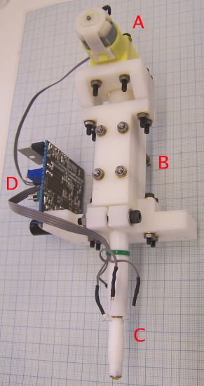
It turns out that it can. Here is a picture of the finished device:
A geared electric motor (A) drives a screw chamber (B) in which a threaded rod is forced against a rod of polymorph. As the thread turns, the polymorph is pushed downwards to a heated nozzle (C) and is extruded out of the bottom. The control electronics is shown at (D).
This Version 2 design has many fewer parts than Version 1, those parts are cheaper and easier to obtain, and the overall mass of Version 2 (just under 200 g) is less than half the mass of Version 1.
The heated nozzle is identical to that used in the Version 1 extruder, and the electronics is only changed by the addition of one potentiometer. The software in the electronics is also identical to that used in the Version 1 extruder. Despite these similarities and identities, full descriptions of all the parts are given in this document for completeness.
I made some parts of the extuder head on a lathe, but it is also possible to make them using a much cheaper alternative. See How to turn on a lathe without one by Vik Olliver for details.
%RED%OBVIOUS WARNING: the heated nozzle C gets very hot (almost as hot as a soldering iron). It is a bad idea to touch it or the wires leading to it when the machine is working or has just recently been switched off.
LESS OBVIOUS WARNING: The motor is geared down to drive the screw-thread very slowly. This means that, even though it is a fairly weedy motor, it is turned with a considerable torque. It is well-nigh impossible to get one's fingers in the works, but if one manages to do so, the motor will just keep going and injuries will occur.
WARNING FOR NON-CHEMISTS: Nozzle C is partially made from PTFE. PTFE is stable up to 250 oC. Above that it breaks down into various gasses, some of which are quite toxic. The extruder should not be operated above 250 oC.%ENDCOLOR%
High-temperature Nozzle
As just indicated, this is identical to the nozzle for the Version 1 Extruder. Vik has an improvement that allows interchangeable nozzles. See it here.
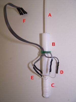
Here is a close up of the heated nozzle (C in the picture above) with a 3 mm Polymorph polymer rod being fed into it.
The 3 mm Polymorph rod to be extruded (A) enters a PTFE tube (B). A smaller brass tube (C) is screwed into the bottom of the PTFE tube. The bottom end of the brass tube forms a fine nozzle. The brass tube is wrapped in PTFE tape, on top of which is wound a coil of nichrome heater wire. The ends of the heater wire can be seen at D. More PTFE tape is wound over the wire to keep it in place and to act as a thermal insulator.
A glass-bead thermistor (the slight bump on the bottom left of the brass tube C) is held against the brass tube by more PTFE tape; the wires from the thermistor can be seen at E. A short four-way ribbon cable is connected to both the heater and the thermistor and terminates in a connector at F. This connector interfaces with the control electronics. The ribbon cable is held to the PTFE tube by the green cable tie.
The nichrome wire heats the brass (C), melting the polymer within it. The PTFE tube (B) guides the solid polymer rod (A) into the brass and insulates the rest of the machine from the high temperature of the brass. As the rod (A) is forced into the top of the PTFE it acts as a piston driving molten polymer out of the nozzle. The thermistor monitors the temperature of the brass and allows it to be thermostatically controlled.
Note the bare flying nichrome wires just below D. These need to be kept clear of the rest of the assembly as shown. They get very hot when the heater is first turned on, and must be in the open air.
To build the high-temperature nozzle, start with the brass tube. This is made from 6 mm diameter brass rod (most of the brass parts of the RepRap machine can be made from this size of rod), but could alternatively be made from a length of M6 threaded brass studding, or from an M6 brass screw from which the head has been hacksawed off.
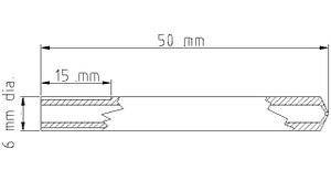
Here is a drawing of the brass tube as it should be when finished. This drawing was created with the open-source version of QCad (Note that the open source version of QCad runs only under Linux. Mind, QCad for Windows at US$31 is not expensive) , and is in the Mechanics folder of the download (see below).
The brass part of the nozzle is a tube 50mm long and 6mm in diameter. The internal hole diameter is 3mm. The left-hand end is threaded M6 for a length of 15 mm. The right-hand end is a fine nozzle formed by a small diameter hole in the end. This is made by drilling the hole, turning a cone on the outside, and then drilling the 3mm hole down the middle from the left. The nozzle is formed by the conical end of the drill, the fine hole, and the external cone.
It was found to be very important to keep the length of the fine-diameter hole that forms the nozzle as short as possible. This is because the resistance to the flow of a viscous fluid (and molten polymer is highly viscous) is very dependent on the length of any tube through which it has to flow.
The diameter of the nozzle is a compromise: a large hole allows material to be deposited fast, but reduces the resolution of the machine; a small hole reduces material deposition rate but allows greater resolution. Most commercial machines use a diameter just under 0.5 mm. Of course, a RepRap machine could have two nozzles: one for coarse infill, the other for surfaces and fine detail. Note that the extrudate will end up slightly larger than the diameter choosen because of die swell (molten polymer is not a Newtonian fluid, it is viscoelastic; this means that when it is momentarily extruded through a fine nozzle it 'remembers' its former diameter and swells a bit larger than the nozzle diameter from which it has emerged). I have not listed tools in the parts section, as all of them are completely standard and widely available. However, fine drill bits are sometimes hard to find, so I have included suppliers of 0.5 mm (and other small) drills.
Start by turning the right-hand end of the rod square, then mark the end with a fine centre drill in the lathe's tailstock. If a fine centre drill is not available, a 1 mm drill projecting just a couple of mm from the tailstock chuck would work just as well. Make only a shallow dent. Next drill the fine nozzle hole using an 0.5 mm drill (other diameters could be used, both finer and coarser) to a depth of about 3 mm. This could be done in the lathe, but I found it easier to use a minidrill in a drill press, with the brass rod held vertically in a vice. Fine drills are very delicate - you need to use minimum force, to make sure you don't bend the drill, and to back off repeatedly to clear the swarf (i.e. use a woodpecker cycle).
Next turn a cone on the end of the rod to form the nozzle. The angle of the cone needs to be rather shallower than the cone created by the 3 mm drill bit that will be used to create the large hole, as in the diagram above. This allows the nozzle's fine-diameter hole to be as short as possible, while giving the greatest strength. When the cone has been turned, the nozzle hole may need to be cleaned again with the fine drill used to make it.
Next turn the left end of the rod flat, and mark a centre on that. Remove the rod from the lathe chuck and offer the 3 mm drill to be used to make the large hole up to the side of it. Position it so that the tip is about 0.5 mm inwards from the tip of the turned cone, then wrap some sticky tape round the other end of the drill to mark the length of the rod. Put the rod back in the lathe and drill it until the tape just touches the end of the rod. That way the hole will be as deep as possible without breaking through at the nozzle end. Once again, it may be necessary to clean the nozzle hole with the fine drill used to make it.
I found it worth wrecking one or two trial nozzles to end up with one where the fine nozzle hole was as short as possible to maximise flow. If you go through, you can always try turning it into an interchangeable nozzle, using an M6 nut to hold on a nozzle of appropriate diameter. This modification is not essential, but unclogs easily and is convenient if you wish to experiment with nozzle diameters.
%GRAY%If studding or a screw is being used to make the brass part of the nozzle (as opposed to plain rod), this paragraph can be ignored. Cut an M6 thread to a length of about 15mm on the rod on the left end. If a lathe is being used, a good way to get the M6 die square for this operation is to put the die in the lathe chuck squaring it up with a rule across the face of the chuck (%RED%unplug%ENDCOLOR% the power first...) and to put the rod in the tailstock. Then put the lathe in its fastest gear to make the chuck easy to turn by hand, and release the tailstock so that it will slide along the bed. Then push the rod against the die and - keeping a slight pressure on - rotate the chuck by hand to cut the thread. Rotate it anti-clockwise occasionally to clear the swarf.%ENDCOLOR%
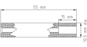
Next make the PTFE tube. Here is a drawing of it (again this is in the Mechanics folder of the download below).
The PTFE tube is 55 mm long and 10.5 mm in diameter. It has a 3 mm hole right through it, and the last 15 mm are drilled and tapped M6. A small cone is cut at the left-hand end so the polymer rod to be extruded can engage in the 3 mm hole more easily. You may find it easier to get 10 mm diameter rod than 10.5 mm; if so only one change needs to be made to the design - this is discussed in the section on the nozzle clamp below.
Cut a length of 10.5 mm diameter PTFE rod and turn the ends square to a length of 55 mm. Drill a 3mm hole right through, and then a larger hole (5 mm) to a depth of 15 mm. Tap this hole M6. (Again, line things up with the lathe: unplug the power, put the tap in the tailstock, set it free to slide, press it against the 5mm hole, and turn the chuck to cut the thread. Do half a turn anti-clockwise every so often to clear the swarf.)
Use a large drill bit to open out the left-hand end of the 3 mm hole into a cone by hand as shown above. This makes it easier for the end of the polymer rod to locate when it is fed into the hole.
%RED%Thoroughly clean%ENDCOLOR% the brass and PTFE parts. Any swarf that remains in them will get swept down by the flowing polymer and will block the nozzle. Screw the parts together tightly, but not so tightly that it strips the threads in the PTFE.
Now wind the heating coil round the brass. I used 0.2 mm diameter nichrome wire, but slightly different diameters would work just as well. Use a multimeter to measure off a 12 ohm length of the wire and cut it (it will be about 200 mm long).
Hold the PTFE tube in a vice with the brass rod projecting horizontally.
Then wrap a helix of PTFE tape round the brass rod so that the helix overlaps itself to give two thicknesses, one on top of the other. This tape is to electrically insulate the nichrome from the brass. If a threaded rod is used the PTFE will pull into the valleys of the thread; this is okay. Alternatively, apply 3 coats of high-temperature BBQ paint, which is rated up to 600C (do remember that the PTFE holder is not for use above 250C though).
Use a blob of Blu Tack or some masking tape to temporarily stick one end of the length of nichrome wire to the PTFE tube where the brass rod is screwed into it and wind the wire in a helix down the brass. If a threaded rod is used you can simply wind it in the valleys of the thread, otherwise you must try to get the pitch reasonably even. Stop about 5 mm from the nozzle end of the brass and wrap a piece of PTFE tape round the last few turns to secure them. Wrap another helix of PTFE tape round the nichrome coil, again overlapping to get two thicknesses. Lead the free bottom end of the nichrome wire straight back up the outside of this to the top of the brass, and wrap more PTFE tape round that to secure it. You should now have something that looks like the photograph above, but without the ribbon cable and without the thermistor wires on the left.
Next, the thermistor. I used the glass-bead thermistor in the Parts List below. It had a beta value of 3500, a room-temperature resistance of about 6 kilohms, and a resistance of about 100 ohms at 170 oC. You could use a different one if need be (there's a spreadsheet in the Electronics section below to help with the calculations), but it needs to be rated up to 250 oC. Carefully wrap the thermistor's leads in PTFE tape to insulate them, then placed the thermistor against the bottom of the brass in the 5 mm gap left below the nichrome coil. Wrap yet more PTFE tape round it and its leads to hold them and to insulate the device. I found that one doesn't need too much insulation - the nichrome is going to have about an amp put through it, and 12 watts will heat things pretty quickly - but the more one has, the more efficient the device will be.
Solder a 150 mm length of four-way ribbon cable to the thermistor leads, using fine heat-shrink sleeving to insulate the join. Soldering to the nichrome is a bit more problematic - solder doesn't wet nichrome... However I found that wrapping both the nichrome and the bared end of the ribbon cable round a single piece of thicker wire (a cut-off resistor lead worked well) would allow solder to be run over the lot (use a little extra flux if it is reluctant to do so) and made a good solid connection. Once again, use heat shrink to insulate them both, but leave all the unsoldered nichrome above the coil in free air - it gets hot.
Attach the ribbon cable to the PTFE tube with a cable tie, taking care not to attach it too near the hot end...
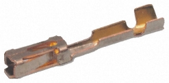
Solder connectors onto the free ends of the ribbon cable. A good cheap way to do this is to get a pack of crimp connectors for unshrouded shells like this:
They are about 12 mm long and 2 mm across. Solder them to the ends of the wires, then put heatshrink sleve flush with the open end round them to insulate them. You finish up with each wire having a neat small individual connector on the end. The connectors are listed in the Parts Section below.
Finally - measuring from the connectors you've just created - check that the resistance of the heater is still about 12 ohms (that is, check that it's not shorting on the brass tube), and check that the resistance of the thermistor is its room-temperature value.
Drive mechanism
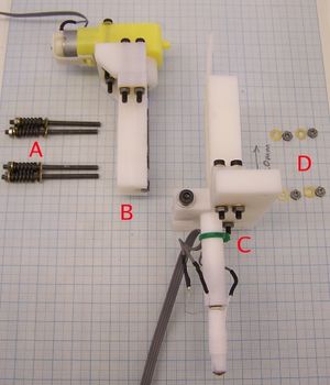
The Version 2 drive mechanism is radically simpler than that for Version 1. Here is an exploded view of it just before the final assembly step:
Four 55 mm lengths of M3 studding (A) have springs on them retained by nuts and washers. These pass through the motor-driven screw block (B) holding it to the polymorph rod guider (C - shown with the extrusion nozzle fitted). The nuts and washers that go on the end of the M3 studding are shown at D. The springs give the device some compliance; slight irregularities in the polymorph rod as it passes through are accommodated, and the force between the rod and the screw-thread driving it is kept roughly constant.
All the rapid-prototyped parts for the extruder were designed using the open-source Art of Illusion (AoI) software package, and the .aoi design files for them are in the Mechanics section of the download below. When you load a design file into AoI you will find that the default viewfield (100) is much too big and the objects are too close. Change that to 5 to see things.
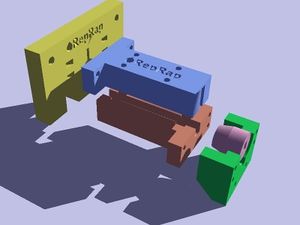
Here is an exploded view of all the rapid-prototyped parts generated by AoI's raytracer. (The raytracer configuration file for this is in the Pix directory of the download below; it's called aoi-raytracer-config.) The exploded view is stored in the assembly.aoi file in the Mechanics directory. Don't use that for design - use the individual files for the parts, then cut and paste any changes into the assembly.aoi file, which is just intended for generating pretty pictures.
The yellow part is the clamp that holds the heated extrusion nozzle. The blue part is the guide for the polymorph rod. The brick-coloured part is the holder for the drive screw. The green part is the geared electric motor mount. And the mauve part is the drive coupling between the motor and the drive screw.
Motor-driven Screw Block
This creates the downward force on the polymorph rod. A motor turns a length of M5 studding that is held against the rod. The studding threads cut into the rod under pressure from the springs (above) and - as it turns - forces the rod downwards into the heated nozzle.
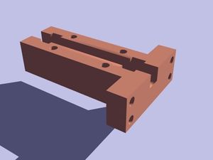
Here is the rapid prototyped part that holds the studding:
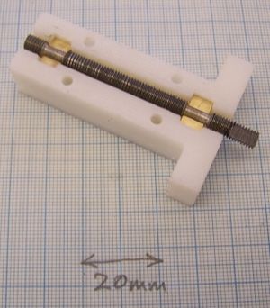
And here is the actual part with the studding fitted:
As you can see, there are two smooth lands machined into the studding that bear on two brass half-round bearings. The right hand end of the studding has two flats filed on it to mate with the drive coupling that will be described below.
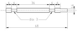
Here are the dimensions of the M5 studding:
The two smooth lands 6 mm long can be turned in a lathe, or using Vik's Afghan Lathe technique (it's a lot cheaper, but as it isn't accurate for work a long way from the chuck, cut the rod 20mm too long at each end so you can put either end in while machining and lop the excess off later). When you file the flats at the right-hand end (they are 8 mm long, to save you arithmetic...) take care to keep them symmetrical; if one is deeper than the other the screw will not turn freely.
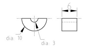
Here is the design of the half-round bearing. An alternative bearing using washers and Polymorph can be constructed if brass rod is not available.
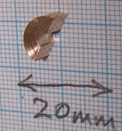
You will need two of these, and they look like this:
Drill a 3 mm hole down the middle of a 6 mm length of 10 mm diameter brass rod, then cut the result in half with a hacksaw. The thickness of the hacksaw blade means that you can't get both bearings from a single whole round - you'll have to make two. So, when you cut them in half, leave a little extra material and finish the part with a file to take it exactly down to the half-way line. I say "exactly" - as long as the 10 mm diameter, the 6 mm length, and the 3mm hole are accurate, the half-way cut doesn't have to be perfect.
Fitting the half rounds into the rapid-prototyped holder can be tricky - they are (deliberately) quite tight. The trick is to put them in at an angle, so one sharp edge is up against the plastic at the place it needs to end up (about 2.5 mm down). Then use a small screwdriver to push the other edge into place. It doesn't matter if they end up at a slight angle - the 3 mm holes will still be in the right place.
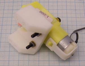
Next, take the motor holder:
And attach the motor to it with two 35 mm M3 cap screws. Make sure you put washers under both the screw heads and the nuts:
Then use four more 35 mm M3 cap screws to attach the result to the thread holder, again not forgetting to use a full set of washers. Fit the drive coupling...
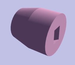
...in between. Note: the tapered end of the coupling is at the screw-thread end, not the motor end; it gives space for the polymorph rod to move past when the device is working.
Lightly grease the places where the studding bears on the brass. This needs to be well-lubricated, but the grease must not get on the polymorph when the device is working.
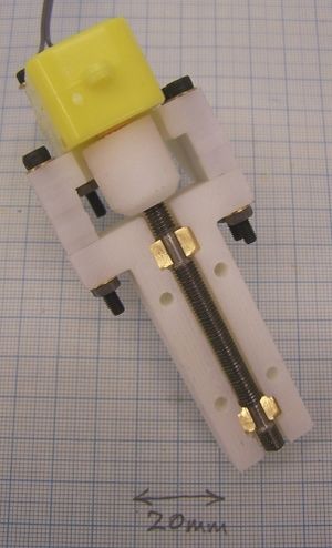
The end result should look like this:
Solder 180 mm leads onto the motor and terminate them with connectors as for the heater wires and thermistor above.
Polymorph Rod Guider
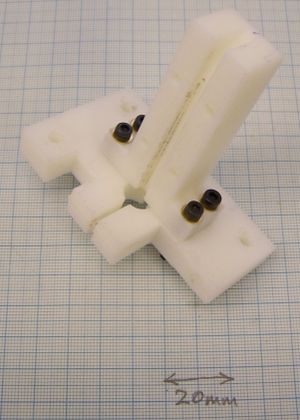
There are two parts to this:
Use four 25 mm M3 cap screws to attach them together using the round holes in the T-shaped guide and the rectangular slots in the clamp like this:
(Did I mention washers? Don't forget them...) Don't tighten the screws for the moment - leave them lose.
Next insert the heated extruder described above into the clamp. You may find this easier if you use a screwdriver as a wedge to open the clamp slightly. Use a 30 mm M4 cap screw, two washers, and a nut to tighten the clamp.
When that is tight, put a 3 mm polymorph (or anything else...) rod into the extruder and use it to line up the T-shaped guide. There are slots in the clamp that allow the guide to be adjusted. When the rod is aligned, tighten the four M3 screws then remove the rod.
The end result should look like this:
Final mechanical assembly
Use four 55 mm lengths of M3 studding to attach the two halves of the extruder together, placing springs sandwiched between washers on one side:
With the polymorph rod in, the nuts should be tightened until the springs have all been compressed by about 3 mm. If you use different springs the force needs to be about 35 N in each one, and you can calculate the compression, x, needed from the spring constant, k using 35 = k.x. If you can't get the springs, 12 mm lengths cut from 6 mm diameter soft plastic tube work well; I tried the tube that bubbles air through aquariums and it worked fine...
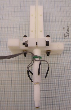
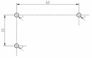
Here is a top-view template for the centres of the M4 holes (radius 2 mm) in the clamp that allow the whole device to be attached to other parts of the RepRap machine:
Electronics
Ultimately, the RepRap machine will be building its own circuitry automatically - you'll just have to plug in the chips. But, while waiting for that, I made the circuit for driving the extrusion head conventionally on 2.54 mm stripboard.
The circuit was designed with the free (but not open source) Eagle PCB designer. Eagle includes a neat routing tool for automatically creating PCBs if you want to etch one, rather than building on stripboard. If you do that, put two 3 mm mounting holes on one edge of the PCB 32 mm apart. All the files for this circuit are in the Electronics directory of the download below.
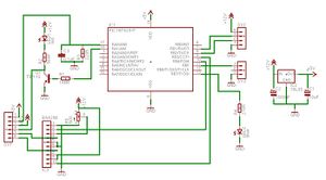
The circuit is based round the PIC 16F628 microcontroller from Microchip Inc.
AN0 is an analogue input. It measures the voltage at the top of R3, which forms a potential divider with the thermistor which is plugged into pins 1 and 2 of of the pin-strip PCB header SV1. C3 smooths the signal. As the temperature of the brass extruder increases the thermistor's resistance falls, so the voltage on AN0 increases.
RA1 is an output. When RA1 is a logical 1 it drives the base of Q1 via R1, turning it on. Q1 is a darlington pair, and so has very high current gain. This means that a quite modest base-current of a couple of milliamps is enough to saturate it. The heater coil is connected across pins 3 and 4 of the header SV1, so - when on - the darlington grounds it, putting almost 12v across it. As the resistance of the heater is about 12 ohms, this gives a current of about 1 amp through the heater and a power output of about 12 watts. LED1 and its current-limiting resistor R2 are in parallel with the heater, so the LED glows whenever the PIC turns the heater on. Q1 is always fully on or fully off, and so doesn't dissipate a lot of heat. However it is worth mounting it on a small heatsink. If TIP110's are in short supply, a TIP31 A, B or C can be used instead but it will need a heatsink and may need a lower value of R1, say 120 ohms.
RB3 and RB4 are outputs connected to the H-bridge motor controller IC3. The motor itself is connected across pins 5 and 6 of the pin-strip header SV1. When RB3 is 1 and RB4 is 0 the motor turns anti-clockwise; when RB3 is 0 and RB4 is 1 the motor turns clockwise. When both outputs are 0 the motor is isolated and stops. The PIC software drives RB3 and RB4 with a variable mark-space square wave to control the motor's speed in both directions using pulse-width modulation. IC3 contains shorting diodes to damp the motor's back EMF when its power is cut. R5 is a 500 ohm potentiometer that controls the peak-to-peak voltage of the pulse-width modulation. It should be adjusted to give a voltage on the pot's wiper of about 7.5 volts. If you use a different motor the trimmer allows you to compensate for different operating motor voltages. But remember that the lower you set the voltage, the more power will be dissipated by IC3 for a given motor current. There are two versions of IC3 (the BA6286 from Rohm) - one with a heatsink, and one without; try to get the one with.
LED2 is driven by software. It is on continuously when the extruder is powerd up but idle, and it flashes when the motor is turning. It doesn't have to be blue, but make the two LEDs different colours so you can tell what's going on more easily.
The pin-strip PCB header SV2 is the power and data connector. The circuit needs a single 12v supply on pin 4 (regulated down by IC2 and its smothing capacitors to 5v for the PIC). Serial data comes in on pin 3 and is transmitted on pin 2. Pin 1 is ground. The serial data is at TTL levels, so if you want to convert it to RS-232 (for example to plug it into a serial port on a PC or a USB-to-serial converter) you need to add a voltage converter chip like the MAX233. Put this on a separate circuit board - the final RepRap machine will do all its internal communication using TTL levels, so ultimately the MAX233 will not be connected to this device.
Header SV3 is an alternative method of control. The software is written so you can turn the extruder on by menu command or by grounding pin 1 of SV3. In the latter case the extruder can act as a dumb device that can be turned on or off with just one logic signal.
Use two 3 mm self-tapping screws to mount the circuit using the location holes in the side of the nozzle clamp. The holes are 32 mm apart.
The voltage at the top of R3 changes non-linearly with temperature, so I have written a spreadsheet to simplify the calculations. It is in the Electronics directory of the download. There are two files: one in .sxc format for OpenOffice (free), and one in .xls format for Excel (not...).
You fill in the five values top-left. The beta value should come from the thermistor's datasheet, and T0 and R0 are the thermistor's room-temperature resistance, which you should be able to measure with a thermometer and a multimeter. The series R value is the value of R3. A good digital multimeter will give you a better value for this than the colour code... The rail voltage is the voltage driving the circuit - in this case 5v from IC2. The T column is temperature in oC, and the R column is the corresponding resistance of the thermistor. The voltage column is the voltage at the top of R3 measured by the PIC. The two columns on the right are the numbers the PIC's analogue to digital converter generates. The PIC has two reference voltage settings - low and high - hence the two columns. You can select which you want at run time (see below). The A-to-D is only four bits (we're not talking precision here), so values are between 0 and 15 (other values in the spreadsheet are spurious - anything below 0 comes out 0; anything above 15 on the high scale is too hot, but it'll stick at 15...). This coarse measurement is, however, good enough to control the extruder's temperature to within 10 oC or so, which is quite adequate.
A different thermistor to the one I used should be easy to accomodate simply by changing R3 so that the A-to-D values around 140 oC come out to about the same numbers. Remember to get a thermistor that is rated up to at least 250 oC.
Software
The software for the extruder is stored in the directory called Software in the download below.
The software is for the PIC and is written in C. It is intended to be compiled using SDCC, and GPUTILS which produce a file called extruder.hex that contains all the information that the PIC needs. How you load extruder.hex into the PIC depends on what sort of PIC programmer you have. If your programmer is compatible with the Picstart Plus programmer from Microchip themselves you can use gpicp. I used SDCC version #1055 (Jul 4 2005).
The program (in src/extruder.c) is divided into sections.
The first section saves the set temperature and speed into the PIC's EEPROM, and restores them on power-up. This means that the PIC remembers them even when it is powerd off then on again. The idea is that you can experiment with values by operating the extruder interactively via its serial interface, and then - once you have got the values right - use it in dumb mode where it is turned on (or off) by grounding (or not) pin 1 of SV3.
The second section contains functions that handle communications with the outside world via the PIC's serial interface. If you have the extruder plugged into a PC (via a level shifter such as the MAX233) you can talk and listen to it with programs like minicom (Unix/Linux) or Hyperterminal (Microsoft Windows). The baud rate needs to be set to 2400. Details of the commands you can give and their meaning are given in the Operation section below.
The third section contains functions that control the heater, the motor, and the blue LED.
The final section contains the initialization function and the main program. The main program runs an infinite loop listening for commands and controlling the peripherals by repeated function calls - i.e. crude process timesharing without interrupts. Note that menu items that need further input %RED%stop the loop until that input is complete%ENDCOLOR%, so once you have typed such a menu-item command letter don't sit scratching your head thinking what hex value to type when the heater is on, for example...
There is a short header file in include/extruder.h that defines a few useful items and some default values.
Under Linux and other Unix variants, you simply type "make" in the Software directory and - if SDCC and the other software are installed correctly - the program should compile and link to produce the extruder.hex file.
There is also a copy of the extruder.hex file in the directory Software/Saved-hex-file, in case you have trouble with the compiler.
At some point I'll publish instructions here for getting everything working under Microsoft Windows and on Macs (if you beat me to it, let me have details...)
Material preparation
Instructions for doing this are available on the Polymorph wiki page.
Operation
Slaken the nuts that compress the springs, place the polymorph rod in the slot that aligns it and push it down into the PTFE and brass tubes. It should move smoothly but tightly all the way to the bottom without jamming.
Tighten the spring nuts. I found that fingernail-tight plus half-a-turn gave about the right pressure, but your fingernails may be different to mine when it comes to using them as a torque wrench. Experiment.
If everything is working properly and the PC serial interface is connected, when you turn the 12v power on to the electronics you should get a prompt like this:
RepRap >
%RED%Note that when the PIC is first turned on after programming it the set temperature and speed are not defined. This means that the heater will probably turn on. Turn it off%ENDCOLOR% %GREEN%immediately%ENDCOLOR% %RED%first time by typing "T00" (without the quotes) at the prompt. This will put the whole machine in idle mode.%ENDCOLOR%
The PIC is then in its main control loop thermostatically setting the temperature and switching on or off the motor and the blue LED. After you've typed "T00" the heater should be off (i.e. the red LED should be off) as the default temperature setting is 0. The motor should also be off, and the blue LED should be on continuously, all of which indicate that the device is idle and awaiting your instructions.
At the "> " prompt you can type a variety of single-letter commands, some of which you need to follow with a single hexadecimal number. Such numbers need to be given as two characters (i.e. they represent one byte), %RED%with the letters in lower case%ENDCOLOR%. Thus "07" (without the quotes) is 7 and "a5" is 165 and so on. When the PIC gives you a hexadecimal number it preceeds it with 0x. You don't do this when you type one.
Here are the commands:
| Letter(s) you type | Meaning |
| t | Return the temperature that has been set as the target temperature |
| T0c | Set the target temperature to 0c (or whatever). Valid numbers are: 00 to 0f |
| v | Return the current temperature measured by the thermistor |
| m | Turn the motor off |
| F | Turn the motor on forwards |
| R | Put the motor in reverse |
| s | Return the currently-set motor speed |
| S80 | Set the motor speed to 80 (or whatever). Valid numbers are: 00 to ff |
| L | Set the analogue-to-digital range low |
| H | Set the analogue-to-digital range high |
| l (lower case L) | Return the analogue-to-digital range (0x01 means low, 0x00 means high) |
Menu items that need further input %RED%stop the main loop until that input is complete%ENDCOLOR%, so, as I said above, don't sit scratching your head thinking what to type when the heater is on, for example... Updates to the software will be interrupt-driven soon.
When the PIC is turned on subsequent to the first time it will recover the temperature and speed setting that you last used before you last turned it off.
The software contains an interlock that stops the motor turning unless the temperature is up to the set temperature minus 1, whatever command you type. Generally you don't want the motor running in either direction unless the Polymorph in the brass tube is melted, as it will be jammed. But (especially when you are setting things up) it is sometimes useful to be able to turn the motor on when the device is cold and there is no rod in it at all. This you can do when the set temperature is 0, as that condition will be satisfied when the device is cold.
If you want to run the motor when there's a Polymorph rod in the machine without moving the rod, simply slaken off all the spring-tightening nuts. The threaded studding then won't drive the rod.
Note also that if you ask the motor to turn on and the device is not up to temperature, the motor will come on later automatically when the set temperature is reached. So don't turn the motor on, see nothing happening, then go for coffee...
As explained in the Electronics section above, the analogue-to-digital convereter in the PIC software is fairly crude, with only 16 possible values from 00 to 0f. The range of temperatures that can be measured and controlled can be further extended by selecting either the low or the high range for the PIC's internal voltage reference. See the spreadsheet for the actual temperatures that the values represent.
Run through the lower-case commands in the table. These report back values rather than changing things.
Then set the temperature to about 140oC (if you use the thermistor I used that's "H" followed by "T09"; get the numbers from the spreadsheet for a different thermistor). Set the speed to "Sf0".
When you first turn the extruder on and set a temperature, the brass tube will come up to that temperature quite quickly. Nonetheless, don't start the motor right away - give the machine a minute or so to stabilise first.
Then set the motor running (the "F" command) and check that it is going in the right direction - the drive coupling should be turning anti-clockwise. If it isn't, stop it with the "m" command and swap the motor leads over.
The Polymorph should extrude well at temperatures around 140oC. Broadly speaking, the hotter it gets, the easier it will extrude.
The machine should extrude polymer whenever the motor is on. There are a couple of seconds delay between the motor starting and stopping and the flow starting and stopping. These are pretty consistent, and so should be easy to allow for in the RepRap driving software.
If you set the motor speed too fast, the polymorph will start to be damaged by the turning thread. You can tighten the springs a bit more, of course, but there is a limit to how far you want to go as the greater the stresses the machine is working under, the less reliable it will be long-term. Increasing the temperature will also speed up the flow, of course.
Once you have the device working, you can switch it off, disconnect the PC and RS232, and just drive it by sending 0 or 1 to SV3 pin 1. Or you can continue to use the serial interface of course. The effects of the "F" command and a 0 on SV3 pin 1 are effectively ORed by the software; either will turn the device on and keep it on. Note that if you turn the device on with the "F" or "R" commands it will continue to run until you type "m" regardless of the state of SV3 pin 1. Similarly, a 0 on SV3 pin 1 will keep the device on even if you type "m".
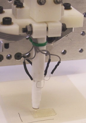
Here it is working
I mounted the extruder on the old Cartesian robot described briefly the the RepRap Blog of 14 May 2005. I set it running to build a 20 mm x 10 mm x 2 mm rectangular block by outlining it and then alternately zig-zag filling it in layers. Here's a picture of the first attempt at making that:
That had the temperature set to 09 (high range) and speed to f0.
Bugs, improvements, and future work
Doubtless this section will get longer with time...
The software needs to be based on Simon McAuliffe's PIC Comms Library so that it can integrate with the rest of the RepRap machine.
The M3 washers need an outside diameter of 7mm or less to avoid overlapping on adjacent holes. If you can't get these, increase the gap between the holes.
M3 Studding cab be hard to get hold of. Enlarging the holes for the M3 studding to M4 appears to work (this has been done manually - and carefully to avoid delaminating the parts - with a sharp drill).
Parts list and sources
If you find a good supplier for a part whom I haven't listed, please let me know. Please give me the URL for the supplier and their part number if you do, though.
Numbers in brackets after links to suppliers are the supplier's part number for the part.
The rapid-prototyped parts obviously have no supplier. The common parts, such as M4 cap screws, can also be obtained at any good hardware or DIY shop, or online engineering suppliers.
Note that many suppliers will only supply much larger quantities than you need of such things as ribbon cable (for which one supplier's minimum is 30 m when all you need is 200 mm...). Maybe you could club together with others who also want to make a RepRap and put in a bulk order.
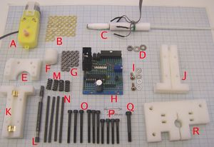
Here is a picture of all the parts of the machine:
The letters in the picture are included in the parts lists below.
Mechanics
| Number off/quantity | Description | Supplier |
| 1 | motor holder (E) | RP part |
| 1 | drive coupling (F) | RP part |
| 1 | polymorph rod guide (J) | RP part |
| 1 | threadded studding holder (K) | RP part |
| 1 | nozzle clamp (R) | RP part |
| 300 mm | steel M3 (1/8") studding (N) | RS (530-292), Farnell (517320) |
| 80 mm | steel M5 (3/16") studding (K) | RS (530-315), Farnell (517343) |
| 18 | steel M3 (1/8") nuts (G) | RS (837-206), Farnell (758796) |
| 36 | steel or brass M3 (1/8") washers (B and I) | RS (560-338), Farnell (149687) |
| 4 | steel 25 mm M3 (1/8") cap screws(P) | RS (376-4555), Farnell (100165) |
| 6 | steel 35 mm M3 (1/8") cap screw (O) | Toolfastdirect (0150M390035) |
| 1 | steel 30 mm M4 (5/32") cap screw (Q) | RS (376-4656), Farnell (8840482) |
| 1 | steel M4 (5/32") nut (D) | RS (525-896), Farnell (149682) |
| 2 | steel or brass M4 (5/32") washers (D) | RS (525-925), Farnell (149689) |
| 60 mm | 10.5 (7/16") mm diameter PTFE rod (C) (you may find it easier to get 10 mm diameter, in which case change the diameter of the corresponding hole in the nozzle clamp; no other modifications are necessary) | Flurocarbon, RS (10 mm: 680-628), Farnell (10 mm: 7174445) |
| 60 mm | 6 mm (7/32") diameter brass rod (C) | RS (682-630), Farnell (7096173) |
| 20 mm | 10 mm (7/16") diameter brass rod (K) | Farnell (7096185) |
| 1 | 0.5 mm drill bit | Modelcraft Collection (N08BN), Farnell (203778) |
| 1 roll | PTFE plumber's tape (C) | any DIY shop, RS (512-238), Farnell (110374) |
| A dab | grease (K) | any DIY shop |
| 4 | 6mm (7/32") diameter 12mm long springs (12 N/mm) (M) - not needed if you use plastic tube instead | Springmasters (C5508120) |
Electronics
The majority of the electronics is shown assembled as item (H) in the picture.
| Number off/quantity | Description | Supplier |
| 300 mm | 0.2 mm diameter nichrome wire (C) | Electronics Plus, Inc. (32-33 AWG is about 0.2 mm dia: 2000BNC-32-1/4), Pelican Wire (32 AWG NICHROME 80); Sciencestore (0.27 mm dia: CB0535), MUTR (0.1 mm dia: EW2 024) |
| 200 mm | 4-way ribbon cable | RS (9-way - divide it: 436-2548), Farnell (3295114) |
| 1 | Thermistor (C) | RS (484-0149) |
| 6 | crimp connectrors | RS (233-1889) |
| 1 | geared electric motor, 3-6v, 200:1 (A) | Greenweld (CDT0302) Pololu (GM3) |
| 1 | 6-way PCB header pin connector (SV1) | RS (479-181), Farnell (32 way - buy one and cut it: 312241) |
| 1 | 4-way PCB header pin connector (SV2) | RS (467-560), Farnell (32 way - buy one and cut it: 312241) |
| 1 | 2-way PCB header pin connector (SV3) | RS, Farnell (32 way - buy one and cut it: 312241) |
| 1 | red LED (LED1) | RS (826-515), Farnell (3350861) |
| 1 | blue LED (LED2) | RS (247-1561), Farnell (233481) |
| 1 | 180R resistor (R1) | RS (144-150), Farnell (513842) |
| 1 | 560R resistor (R2) | RS (144-217), Farnell (513969 |
| 1 | 220R Resistor (R3) | RS (144-166), Farnell (513866) |
| 1 | 270R Resistor (R4) | RS (144-172), Farnell (513880) |
| 1 | 500R trimmer pot (R5) | RS (374-7027), Farnell (107616) |
| 1 | 10 uF electrolytic capacitor (C1) | RS (768-728), Farnell (4311267) |
| 1 | 1000 uF electrolytic capacitor (C2) | RS (228-6694), Farnell (3036420) |
| 1 | 0.1 uF capacitor (C3) | RS (829-615), Farnell (3549811) |
| 1 | TIP110 darlington pair (Q1) | RS (485-9648), Farnell (4347353) |
| 1 | PIC16F628-P microcontroller (IC1) | RS (379-2869), Farnell (3154786) |
| 1 | 78L05 voltage regulator (IC2) | RS (810-295), Farnell (412430) |
| 1 | BA6286 motor-control H bridge(IC3) | RS (245-6045) |
| 1 | 18 pin DIL chip socket (for IC1) | RS (813-143), Farnell (4242373) |
| 100 mm | 2 mm dia. heatshrink sleve | RS (366-2847), Farnell (236482) |
| 2 | 5 mm M3 self-tapping screws (I) | RS (521-383) , Farnell (593394)
|
Material
The RepRap Polymorph page gives a list of suppliers for the material.
Design and software downloads
To download all the associated design files in gzipped .tar format as a single file (23 MB), click here: extruder-v2.tgz.
On Unix/Linux run the file through gunzip and then tar.
gunzip extruder-v2.tgz tar -xvf extruder-v2.tar
With GNU tar these steps can be conflated:
gtar -xvzf extruder-v2.tgz
Under Microsoft Windows, Winzip will unpack the archive.
The result will be a single directory called extruder-v2 which contains:
drwxr-xr-x 2 ab users 4096 Sep 5 15:38 Electronics -rw-r--r-- 1 ab users 25267 Sep 5 15:46 LICENCE drwxr-xr-x 2 ab users 4096 Sep 5 15:42 Mechanics drwxr-xr-x 2 ab users 4096 Sep 6 18:04 Pix -rw-r--r-- 1 ab users 238 Sep 5 15:29 README drwxr-xr-x 8 ab users 4096 Sep 5 17:48 Software
The Electronics directory contains the circuit diagram and the thermistor calculation spreadsheet.
The LICENCE file is the GNU Public Licence.
The Mechanics directory contains the AoI CAD and STL files for the RP parts, and the DXF files for the drawings.
The Pix directory contains all the images used in this page, and the high-resolution originals of them.
The README file is, I hope, reasonably self explanatory.
The Software directory contains the program that needs to be downloaded into the PIC.
Alternative ThermoplastExtruder Designs
Clanking Replicator Project: Tommelise Fused Deposition Modelling (FDM) Extruder 1.0
The Tommelise FDM Extruder 1.0 derives from the RepRap Thermoplast Extruder 2.0 to the point of using its ABS parts kit. It a higher power 2 amp extruder barrel and a modified polymer pump that allows it to extrude several other plastics besides polycapralactone. You can access documentation on the Tommelise FDM Extruder 1.0 at...
http://3dreplicators.com/New%20Front%20Page/Documentation/Extruder/Mk%201%20Polymer%20Pump.htm
Potential adopters of this design should note that minor but necessary changes to both the firmware of RepRap extruder controller board and its design will be required to full capabilities of this alternative extruder.
License
RepRap is copyright 2005 University of Bath, the RepRap researchers (see the project's People page), and other contributors.
This web page and all the other files in its download are covered by that copyright.
Principal author:
Adrian Bowyer Department of Mechanical Engineering Faculty of Engineering and Design University of Bath Bath BA2 7AY U.K. e-mail: [email protected]
RepRap is free; you can redistribute it and/or modify it under the terms of the GNU Library General Public Licence as published by the Free Software Foundation; either version 2 of the Licence, or (at your option) any later version.
RepRap is distributed in the hope that it will be useful, but WITHOUT ANY WARRANTY; without even the implied warranty of MERCHANTABILITY or FITNESS FOR A PARTICULAR PURPOSE. See the GNU Library General Public Licence for more details.
For this purpose the words "software" and "library" in the GNU Library General Public Licence are taken to mean any and all computer programs computer files data results documents and other copyright information available from the RepRap project.
You should have received a copy of the GNU Library General Public Licence along with RepRap; if not, write to the Free Software Foundation, Inc., 675 Mass Ave, Cambridge, MA 02139, USA, or see
http://www.gnu.org/
