Template:RepRapPro hot end assembly
Contents
Tools
You will need the following tools:
- Allen key
- Small screwdriver
- Pliers
- Adjustable spanner
- Heat sources (small blowtorch plus hairdryer/soldering-iron)
- Bench vice
Parts
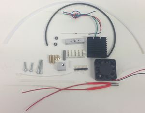
You will see that Mendel and Huxley have different connecting wires. Also the Huxley heating resistor is a 6R8, whereas the Mendel one is 2R7.
There are also alternative crimps for attaching the wiring to the resistor and thermistor (red rectangle). See below.
There are several stages in this construction where you have to trim pieces of PTFE. It is essential to clear any swarf created away and not to let it get into the extruder. PTFE swarf will travel to the nozzle and block it if it is allowed to contaminate the device.
Step 1: The hot part of the hot end
Check that the heater resistor fits in the larger hole in the heater block. The resistors can be a little variable in their diameter. The thermistor should fit in its hole - they are manufactured to a tighter tolerance.
If the resistor is too big, clamp the heater block firmly in a vice and run a 5mm drill down it. Be careful to run it square on. Running the drill up and down will shave a little off the sides of the hole. Repeat this until the resistor fits.
Set the resistor aside for use in a minute.
Take the PTFE tube from the extruder drive that you just made. If you have the 3mm diameter version, cut a short length (about 15mm) from its free end using a sharp blade, taking care to make the cut square on to the axis of the tube. Put the short length aside for use later.
If you have the 4mm diameter version you will also have a short length of 3mm diameter in your kit. In the 4mm diameter tube case, use a pencil sharpener to make a small cone on about 2mm of the free end of the 4mm tube. Take care not to cut too far - PTFE is very soft.
Screw the brass union onto the end of the PTFE tube that you have just cut. By looking down the other end of the brass you will be able to see when the PTFE reaches the end of the thread (a magnifying glass is useful here).
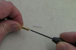
Screwing the tube in will have reduced its internal diameter slightly. Gently twist a 2mm drill by hand in the end of the brass to thin the tube where it is inside the screw thread. If you have a small hand-chuck this is made easier:
Push a length of 1.75mm build filament down the tube from the other end to clear out any PTFE swarf (see the warning above about leaving any behind). Make sure the filament runs freely down the tube and comes out of the far end without impediment.
Wrap plumber's PTFE tape round the shorter thread of the stainless steel barrel BUT NOT the nozzle:
Take care that the tape does not cover the holes, and leave the smooth part of the barrel free (or trim the tape away from that with a blade after wrapping). The barrel has a big temperature drop in operation from one end to the other (around 200oC), so it is important that you leave the middle surface free to radiate heat.
Don't put PTFE tape on the nozzle.
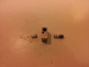
Screw the barrel and the nozzle into the heater block so they meet in the middle. The nozzle goes in the side of the aluminium block with the small 2mm through-hole (that will later accommodate the temperature-measuring thermistor).
Offer up the PTFE insulating cone beside the nozzle. The nozzle should stick out of the block a bigger distance than the depth of the cone. The cone will be screwed onto the nozzle later, and the nozzle needs to project out the bottom.
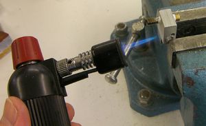
Place the assembly in the corner of a vice, gripping as little of it as is compatible with its being secure. Adjust the adjustable spanner to the flats on the nozzle and have the long-nosed pliers to hand.
Use the blowtorch to heat the block:
You need to heat the block enough for it to expand by at least the amount it will expand during printing. Neither the brass nozzle nor the stainless steel barrel will expand as much as the aluminium heater block. So, whilst hot, hold the steel coupling with the pliers and tighten the nozzle with the spanner. This will normally take only a very small amount of rotation (say 1 or 2 degress) but will be enough to ensure the nozzle assembly does not leak during printing.
Leave the block in the vice to cool.
Step 2: The cooling system
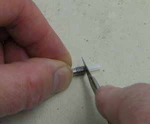
Take the short length of PTFE tube you saved and put it in the counterbored hole in the stainless steel barrel. Trim it flush with a sharp blade:
Take a 5mm drill and gently twist it against the end of the PTFE that you have just created to dish it slightly. Make sure you clear all swarf away.
Now screw the brass bowden end piece (with the PTFE bowden tube screwed into it), into the Aluminium heatsink block (the long thin one with five holes in it). Once fully screwed in, screw the free end of the barrel into the M5 hole in the Aluminium heatsink block until it meets the brass piece. Now unscrew the brass piece by 1/4 turn, screw the barrel in to meet it, and finally tighten the brass piece with some pliers. This will result in the barrel and bowden end pieces being locked together inside the heatsink block.
The heater block should be parallel with the heatsink block (and with the power resistor).
Peel the sticky backing off the fan and heatsink. This is quite tough - you may need to pull with pliers. Take care not to put stress on the delicate plastic fan. The easiest way once you have a corner off is to hold that with long-nosed pliers and to roll them over the back face of the heatsink like peeling the lid off a tin of sardines.
If you are building a Huxley, keep the sticky backing - you will need it on the next page. Cover the side that was against the fan with polythene (such as the zip bags that the components come in are made from) and keep the plastic covering on the other side.
You can put a little heatsink grease on the aluminium cooling block if you like. Attach it to the fan with the two longer screws. Put the two shorter screws through the PTFE spacer and screw them a few turns into the block.
You will see that there are slots in the heatsink attached to the fan that blow down on the heater block. Put a piece of sticky tape over those slots.
Step 3: The heater resistor and temperature-measuring thermistor
If the heater resistor is too lose in its hole in the heater block, wrap it in a little PTFE tape.
For Mendel use two adjacent wires from the ribbon cable for each end of the heater resistor - four in all. This is to increase the current capacity. For Huxley, simply connect one wire to each end.
For Mendel the wires across the ribbon cable in order go like this:
- Wire with the colour stripe: Thermistor
- Thermistor
- Fan + volts
- Fan Ground
- Heater resistor Wire 1
- Heater resistor Wire 1
- Heater resistor Wire 2
- Heater resistor Wire 2
Resistor wires 1 and 2 are arbitrary - the resistor has no polarity.
You can either use the ferrule crimps (right in the red box in the parts picture) or the connector crimps (left). The connector crimps just plug onto the resistor and thermistor wires, which is simple. The ferrule crimps are a bit more fiddly, and they make a permanent connection.
The advantage of the connector crimps is that you can plug and unplug the wires. The advantage of the ferrules is that they give a better quality (i.e. lower resistance) connection.
Alternative 1: Ferrule crimps
The pictures show the ferrule crimps and the Huxley single wires.
Bare about 10mm on the end of the resistor connector wires and crimp them onto the ends of the resistor's leads. Put heatshrink on and use a soldering iron or hairdryer to shrink it.
The picture shows the left-hand side complete, and the right hand side waiting for the crimp to be slid over the join followed by crimping. It also shows conventional heatshrink. To shrink the PTFE heatshrink you will have to hit it with a flame - a mere soldering iron won't touch it.
The thermistor should fit in its hole - they are manufactured to a tighter tolerance. It will be a little undersized. But the crimps on the thermistor wires won't fit through the hole, so you have to crimp one wire after the thermistor has been pushed through the block.
Put about 20mm of PTFE heatshrink over the thermistor and shrink it on with a flame (try not to scorch things). Put the thermistor in the block - the PTFE should make it a snug fit. Crimp and then heatshrink over the connections to either end. With the ribbon cable for the second thermistor connection, don't forget to slide the heatshrink onto it and away from the join before you make the join - you won't be able to get it on afterwards.
Alternative 2: crimp sockets
Simply crimp the sockets on the ends of the thermistor and heater resistor wires, then shrink black heatshrink over them to insulate them. For Mendel remember that each end of the heater resistor needs two wires - bare them and twist the ends together before fitting the crimp sockets.
Connecting up
Bend the wires up the side of the heat sink. Do not pull them tight - they need a little slack to accommodate movement and expansion. Attach them at the top of the heatsink with two cable ties chained together, one of them running through the top slot in the heatsink.
Trim the excess off the cable ties.
Use a meter to check that the resistance between the wires and the aluminium block is infinite and that nothing is shorting.
Step 4: Fan wires and nozzle insulator
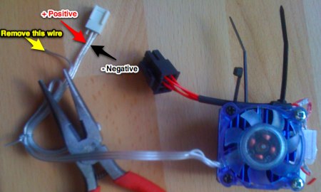
You need to cut one wire off the fan. Looking at the picture below, use a red and a black felt-tipped pen to mark the positive and negative fan wires. Trace them right back to the fan and mark them there.
Cut the socket off (leaving your marks on the fan side of the cut...), then remove the extraneous wire.
Screw the PTFE insulating cone onto the nozzle.
