TMC2660-Dual Stepper Board
Release status: Experimental
| Description | TMC2660-PA Dual Stepper Board
|
| License | GPLv3+
|
| Author | |
| Contributors | |
| Based-on | |
| Categories | |
| CAD Models | Eagle
|
| External Link |
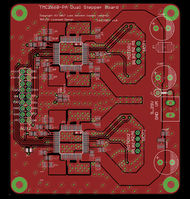
Dual TMC2660 Expansion Board
A 70x78mm expansion board providing two 2.2A (RMS) / 2.8A (RMS) boost current Trinamic TMC2660 stepper drivers, designed for general-purpose use on a wide range of 3D Printing Electronics, powered from 9-29 volts DC, compatible with 3.3v and 5v boards, and providing an on-board NTC temperature resistor, dual STEP/DIR/EN for motor control and an SPI-based interface for configuration of both drivers.
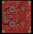
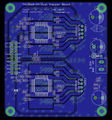
Prototype
Features:
- Two independent TMC2660-PA steppers
- Experimental 2-layer (1oz copper) design
- Relatively large PCB to support proper thermal dissipation (70x78mm)
- 1 on-board 100k NTC with a 4.7k bias
- compatible with 3.3V or 5V electronics
- Supports Motor DC Power input from 9 up to 29 volts.
- 18-pin 2.54mm DIL Header with 1 ADC (thermistor), 2 sets of STEP/DIR/EN, and SPI. (I2C unused: for future use)
Design considerations
The TMC2660 is sufficiently high current to make it unsafe to put onto a polulu (postage-stamp-sized) PCB: Trinamic's application notes advise a minimum of 20 mm^2 for safe thermal dissipation. Also, the TMC2660 realistically has been designed for use on a 4-layer PCB: STEP, DIR and VCCIO are topologically trapped (surrounded) by VMOT, GND, and the Motor Output pins.
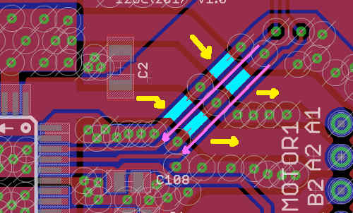
An initial experimental design attempted to cross the STEP, DIR and VCCIO over the 2mm-wide motor output tracks:
Marked in yellow is where the Motor output (power) tracks travel, on the BOTTOM layer. STEP and DIR (purple) come in at right-angles on the TOP layer. In cyan, Ground tracks separating STEP and DIR and joining in a criss-cross fashion to BOTTOM. Bridging across a 2mm gap is quite excessive and may still result in EMI interference: however the TMC2660 produces good quality output so this may not be an issue.
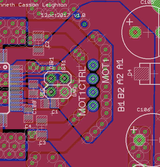
There is however another solution: given that STEP, DIR and VCCIO are trapped, place a 4-pin header in the centre, surrounded by GND and VM (Motor DC power in). This requires separate flying leads for each motor control, but this is not so hard to do, given that the advantage is a much-reduced cost of production of the PCB (only 2-layer) and the fact that it brings the TMC2660 into the realm of DIY / Home electronics.
If this was a single-board solution with an integrated MCU, this would not be possible to achieve (without having a flying lead). However as it is an expansion board anyway, making up a wiring loom that goes to three separate headers is a cost-effective way to solve the problem.
AUX2 Header
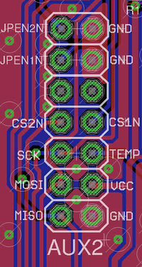
AUX2 is an 18-pin (2x7) header at the left of the board. Pin 1 is marked (bottom right, row 9). This header has nine GPIO and SPI. Four pins per stepper are required: EN, CS, STEP, DIR. The ninth pin is an ADC and is connected to a 100k NTC thermistor in the middle of the PCB. It may be used to check the temperature, to detect if the PCB is overheating. Note that pins 13 and 14 are reserved for I2C. Future versions of TMC2660-DSB may have I2C ICs on-board.
- Pin 18 (row 1, left): MOT1EN# - pull low to enable
- Pin 17 (row 1, right): GND
- Pin 16 (row 2, left): MOT2EN# - pull low to enable
- Pin 15 (row 2, right): GND
- Pin 14 (row 3, left): SCL (Unused: do not use or connect)
- Pin 13 (row 3, right): SDA (Unused: do not use or connect)
- Pin 12 (row 4, left): CS2# - Motor 2 SPI ChipSelect - pull low to enable
- Pin 11 (row 4, right): CS1# - Motor 1 SPI ChipSelect - pull low to enable
- Pin 10 (row 5, left): SCK
- Pin 9 (row 5, right): ST1 - Motor 1 Step
- Pin 8 (row 6, left): MOSI
- Pin 7 (row 6, right): DIR1 - Motor 1 Dir
- Pin 6 (row 7, left): MISO
- Pin 5 (row 7, right): DIR2 - Motor 2 Dir
- Pin 4 (row 8, left): 100k NTC Thermistor, 4.7k biased.
- Pin 3 (row 8, right): ST2 - Motor 2 Step
- Pin 2 (row 9, left): Power (3.3v for Due, 5.0v for 2560)
- Pin 1 (row 9, right): GND
