TMC2209
I am trying to make a compilation of information about TMC2209 stepstick drivers that are available out there.
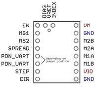
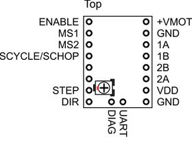
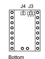
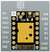
There seems to be a great variation of how the UART pins are brought out to the edge connectors of the stepstick boards, and I would like to get some clarification on this matter.
Contents
On-chip 5V regulator
Please note that there is an internal 5V linear regulator, on the chip itself, and the about 20mA that the logic on the chip uses, will cause the following heat dissipation at different stepper supply voltages[1].
- 0.1W @ VM=12V
- 0.3W @ VM=24V
- 0.6W @ VM=36V
- 0.8W @ VM=45V
So a heat sink, that can help remove this heat from the board/chip, should always be used.
Good Heat Sink sizes. The bigger the better:
Hardware
Watterott
Design files: https://github.com/watterott/SilentStepStick
Versions: V2.0
Pictures:
Pinout details:
Panucatt
Design files: http://panucattdevices.freshdesk.com/support/solutions/articles/1000285641-new-sd2209-drivers
Versions: V1.0
Pictures:
Pinout details:
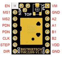
BTT
Design files: Ver 1.1 Github, Ver 1.2 Github
Versions: V1.1, V1.2
Pictures:
Pinout details: for V1.1 and V1.2
Fysetec
Design files: https://wiki.fysetc.com/Silent2209/
Versions: V2.1, V3.0
Pictures:
Pinout details:
- I am not quite sure what to show here, as I find the fysetec wiki page a little confusing. So please go and see for yourself.
- And once you have tested an actual board, please update this page.
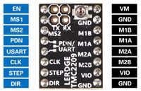
Lerdge
Design files: hmmm...
Versions: V1.0
Pictures:
Pinout details:
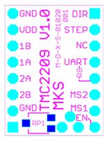
makerbase
Design files: https://github.com/makerbase-mks/MKS-TMC2209
Versions: V1.0
Pictures:
Pinout details:
Firmware
Marlin 2.0.x
Below are listed some controller boards, and pin definition files, and default pins used for UART communication with the TMC2209 stepper drivers
Mega RAMPS
definitions in file: github \Marlin-2.0.x\Marlin\src\pins\ramps\pins_RAMPS.h
   #define X_SERIAL_TX_PIN  40
   #define X_SERIAL_RX_PIN  63

   #define Y_SERIAL_TX_PIN  59
   #define Y_SERIAL_RX_PIN  64

   #define Z_SERIAL_TX_PIN  42
   #define Z_SERIAL_RX_PIN  65

   #define E0_SERIAL_TX_PIN 44
   #define E0_SERIAL_RX_PIN 66
Here is a forum entry about how to do a Single Pin SoftwareSerial for each stepper driver using the Arduino Mega, with a RAMPS board Reprap Forum thread
   #define X_SERIAL_TX_PIN  63
   #define X_SERIAL_RX_PIN  63

   #define Y_SERIAL_TX_PIN  64
   #define Y_SERIAL_RX_PIN  64

   #define Z_SERIAL_TX_PIN  65
   #define Z_SERIAL_RX_PIN  65

   #define E0_SERIAL_TX_PIN 66
   #define E0_SERIAL_RX_PIN 66
Notes about Software serial pins on Arduino Mega pins:

Issue is software serial and interrupts
the RX pins needs to be a 'change interrupt capable pin' on the mega

"Not all pins on the Mega and Mega 2560 support change interrupts, so only the following can be used for RX: 10, 11, 12, 13, 14, 15, 50, 51, 52, 53, A8 (62), A9 (63), A10 (64), A11 (65), A12 (66), A13 (67), A14 (68), A15 (69)."

There is a difference between 'General Interrupt pins' (on the Arduino Mega) that can be used
via attactInterrupt() in Arduino) - and then the pins where the
Software Serial library can deal with "Change State" interrupts.

So there is no need to use pins 2,3, 18,19 or 20,21 for Software Serial.
See also: Forum thread discussion about 2209 and software serial
Re-ARM RAMPS
definition in file: github \Marlin-2.0.x\Marlin\src\pins\lpc1768\pins_RAMPS_RE_ARM.h
    #define X_SERIAL_TX_PIN  P0_01   // Mega:D21  I2C-SCL
    #define X_SERIAL_RX_PIN  P0_01

    #define Y_SERIAL_TX_PIN  P0_00   // Mega:D20  I2C-SDA
    #define Y_SERIAL_RX_PIN  P0_00

    #define Z_SERIAL_TX_PIN  P2_13   // Mega:D34 - RAMPS:E2-Dir
    #define Z_SERIAL_RX_PIN  P2_13

    #define E0_SERIAL_TX_PIN P2_08   // Mega:D36 - RAMPS:E2-step
    #define E0_SERIAL_RX_PIN P2_08
