Stepper Motor Driver 1.1
Contents
Stepper Motor Driver v1.1
Overview
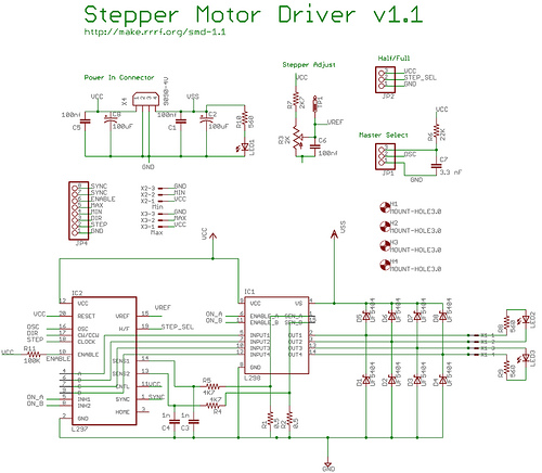
This board allows you to control one stepper motor, as well as receive input from two limit switches. It is based around the L297/L298 stepper driver combo. The L297 takes the signals from your microprocessor and translates them into stepping signals to send to the L298 which actually drives your stepper motor. The L298 is capable of driving up to 2A per coil. One interesting feature of the L297 is its current sensing and 'chopping' abilities. The L297 will sense the amount of current flowing through the coils, and will 'chop' the signal to the L298 so that the average current flowing is the desired amount. You can configure this current by setting the trimpot on the board.
At the bottom of the page is a section showing how to run this board off a single 12v supply. This will allow you, for example, to run your RepRap machine off a car battery if you want.
- You'll need a soldering toolkit to do most of this.
- Read our Electronics Fabrication Guide if you're new.
Get It!
Full Kit
Raw Components
Files
You can download the release file from SourceForge that has a bunch of helpful files for this board. It contains:
- GERBER files for getting it manufactured
- PDF files of the schematic, copper layers, and silkscreen
- Eagle source files for modification
- 3D rendered image as well as POVRay scene file
- exerciser code to test your board.
Schematic
Interface
Input/Output Row
| Pin | Function |
| GND | Connect this to Arduino to share a common ground. |
| Step | A pulse on this line will make the stepper motor advance one step in the desired direction. |
| Dir | If this pin is high, the motor will rotate forward, low it will rotate backwards. |
| Min | This is the signal from the 'X min' sensor. high means open, low means closed. Pin closest to board edge is +5v, middle is signal, farthest is GND. |
| Max | This is the signal from the 'X max' sensor. high means open, low means closed. Pin closest to board edge is +5v, middle is signal, farthest is GND. |
| Enable | Optional This pin allows you to turn the motor on and off. By default it is pulled high. A high signal means on, low signal means off |
| SYNC | Optional In slave mode, you will need to connect this to the SYNC of a board set to be master. |
| SYNC | Optional In slave mode, you will need to connect this to the SYNC of a board set to be master. This pin is the same as the one above, its just here so you can chain boards together easily. |
Output
The L298 is rated for 2A per coil, so if your stepper motor drives more than that, you should adjust the chopper so that it delivers less current than that.
| Pin | Function |
| Stepper | This is the output for the stepper motor. |
We have a page with info on wiring your stepper motor.
Jumpers
There are certain things that can be configured on this board by setting jumpers. Make sure you set all the required jumpers.
S M
This is the slave/master jumper setting. Putting a jumper on the side closer to 'S' makes it a slave, and closer to the 'M' makes it a master. The master generates the oscillation, as well as sync pulses for the other boards. You will want to pick one board as the master, and set the rest to be slaves. It really doesn't matter which is master and which is slave, so long as there is only one master, and the rest of the boards are slaves.
It turns out that you can also just set all your boards to 'Master' and ignore the 'Sync' lines. Works just fine for me - Zach
You need to select a mode for your board to run!
Steps
This is how you select half vs. full stepping. Half stepping means the stepper takes twice as many steps, whereas full stepping means the stepper takes its normal number of steps. Half stepping is highly recommended.
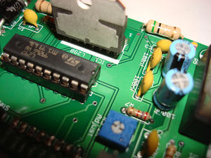
Current Adjustment
The board allows you to control the amount of current flowing through the coils by adjusting a trimpot located on the board below the 'Max' header. Simply turn the trimpot one direction to get the minimum current, and the other direction to get maximum current. Generally this will be clockwise/counter clockwise, but it will be obvious which is which as you adjust the current with the motor running. Adjusting it to the lowest setting will cause the motor to stop turning. Generally, you will want to adjust this to the lowest setting you need that will still turn the motor. That will reduce power usage, and will prevent your motor from overheating.
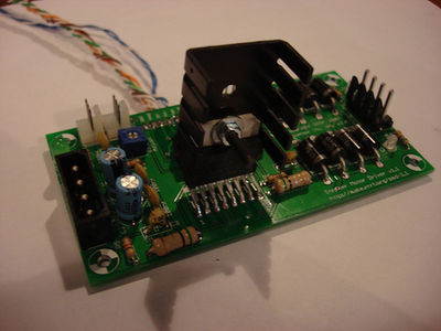
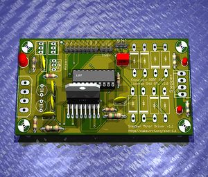
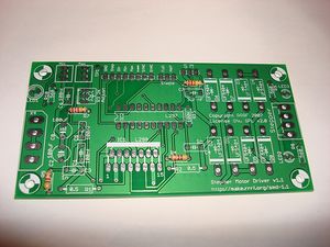
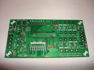
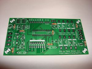
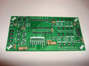
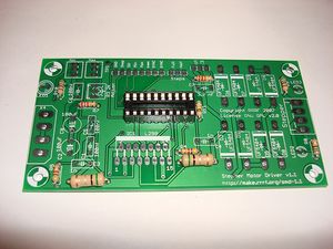
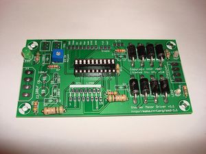
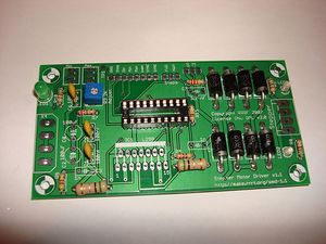
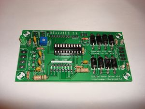
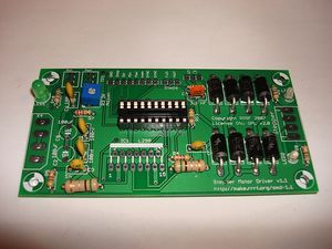
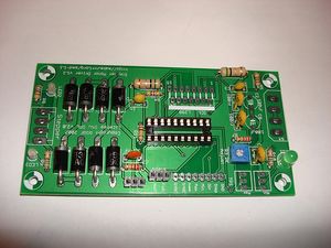
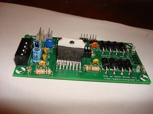
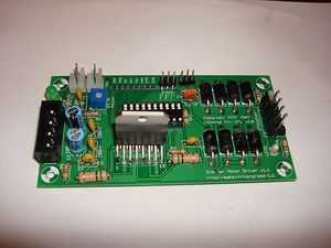
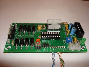
Circuit Board
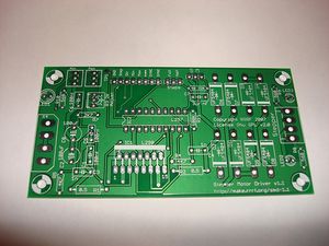
You can either buy this PCB from the RepRap Research Foundation, or you can make your own. The image above shows the professionally manufactured PCB ready for soldering. Its also cheap, only $7.50 USD.
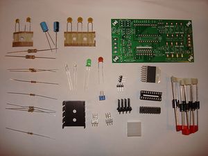
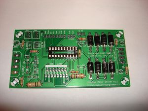
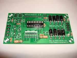
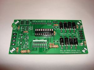
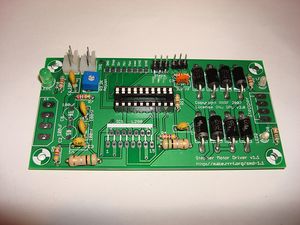
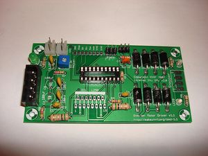
Components
Notes:
- I forgot the power connector in this picture. You still need it =)
- The silkscreen says UF5404, and the BOM specifies SB360 diodes. Both will work, but I think the SB360 are cheaper/more readily available.
<iframe src="http://parts.reprap.org/embed/module/Stepper+Motor+Driver+v1.1" width="600" height="800" frameborder="0">Visit http://parts.reprap.org/embed/module/Stepper+Motor+Driver+v1.1</iframe>
Known Bugs
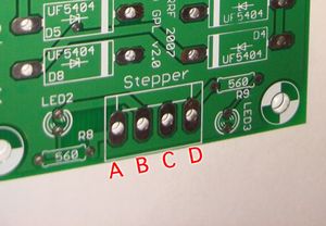
- I forgot the silkscreen on the motor output, you should label them for easy reference. See the output interface notes above.
Build Process
R4, R5
These are 4.7K ohm resistors. Solder these resistors in the appropriate places. Make sure you double check the color codes to make sure you're putting the proper resistor in the proper place. You can insert the resistor in any orientation into the board.
R6
This is a 22K ohm resistor. Solder this resistors in the appropriate places. Make sure you double check the color codes to make sure you're putting the proper resistor in the proper place. You can insert the resistor in any orientation into the board.
R7
This is a 2.7K ohm resistor. Solder this resistors in the appropriate places. Make sure you double check the color codes to make sure you're putting the proper resistor in the proper place. You can insert the resistor in any orientation into the board.
R8-R10
These are 560 ohm resistors, used to limit the current flowing through the LEDs. Solder these resistors in the appropriate places. Make sure you double check the colour codes to make sure you're putting the proper resistor in the proper place. You can insert the resistors in any orientation into the board.
R11
This is the 100K ohm resistor hiding at the base of IC2. Make sure you double check the colour codes to make sure you're putting the proper resistor in the proper place. You can insert the resistor in any orientation into the board. Inserting from the printed side is the recommended method.
R1, R2
These are the bigger, 0.5 ohm resistors with thicker leads. More challenging to thread through. Solder these resistors in the appropriate places either side of IC1. You can insert these resistors in any orientation into the board.
Socket
Now is a good time to solder the DIP socket into the board. Try to get it as flush with the board as possible. I like to solder a corner pin, then solder the opposite corner pin to lock the socket into place as I solder the rest.
D1-D8
First insert all the diodes into place. Bend the leads with your hands or with some pliers, as close to the body as you can. Then, insert the component so that the band one one end matches up with the band on the silkscreen. Make sure you get these right!!! After you have inserted all the components, flip the board and solder them all in.
LED2, LED3
These are the bicolor LEDs. Orientation does not matter a whole bunch, but its a good idea to put the short leg into the hole nearest the flat part on the silkscreen.
LED1
This is the power on LED. Orientation is important, so make sure you put the short leg into the hole nearest the flat part on the silkscreen. The LED itself should also have a flat side, which should match up to the silkscreen.
If you have LEDs with flats midway up the legs, they will not fit properly. You can either accept leds not being flush with the board, or clip the legs above the flats, while being careful to keep an eye on polarity when you insert the LEDs.
R3
This is the trimpot. There are numbers on it, that match up with the numbers on the silkscreen. Insert it accordingly, and solder it in. If it is inserted incorrectly, it will not ruin your board, but the current increase direction will be reversed.
Note: the trimpot component has changed since the board design was released. We now use one with pins arranged in a triangle. Simply bend the middle pin towards the other two and solder in as normal.
C1, C5, C6
These are the 100nF ceramic capacitors. They will have something like '104' written on the side. Solder them into place, orientation does not matter.
C3, C4
These are the 1nF ceramic capacitors. They will have something like '102' written on the side. Solder them into place, orientation does not matter.
C7
This is the 3.3nF ceramic capacitor. It will have something like '332' written on the side. Solder it into place next to the diodes. Orientation does not matter.
JP1, JP2
These are the headers for the jumpers. Break off the appropriate number of pins from the pin strip and solder them into place. Take care to make sure you solder them in straight.
X2, X3
These are the headers for the min/max switches. insert them so the tabs are facing inside the board.
POWER
This is the power connector for the board. It is a standard socket that accepts a power cord from a standard PC power supply. Match up the notches on the inside of the connector with the markings on the silkscreen. Solder it in, and make sure you use plenty of solder.
C2, C8
These are the electrolytic capacitors. They have only one orientation you can solder them in. One side is marked negative (with '-' going down one side.) The other lead is longer and should be inserted into the hole marked '+'.
The PCB hole spacing is incorrect, so you may have to bend the legs slightly to get them to fit properly.
IC1
This is the L298 chip. You will only be able to insert it into the board in one orientation. We messed up on this board, so its recommended that you attach the heatsink before you insert it so that you know the heatsink will fit. Once you have inserted it, solder it in. Take care not to use too much solder so that it doesnt bleed through and bridge where the leads come together.
X1
This is the stepper header. Solder it with the tabs facing the inside of the board. Make sure it is nice and flush with the board. If you ordered it from Mouser, it comes as part of a breakaway header. Use wire clippers to cut the plastic joiners apart to make it the correct width.
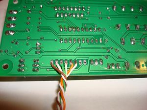
Input Wires
Take 2-3 feet of Cat 6 ethernet cable, and remove 1" of the sheath from it to expose the twisted pairs. Trim 1/4" from the end of each of the wires, and insert them into the respective holes for the pins. Then solder each wire into its hole. Trim the ends if required.
| Color | Input |
| GND | Brown |
| Step | White/Brown |
| Dir | Green |
| Min | White/Green |
| Max | Orange |
| Enable | White/Orange |
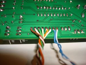
Its recommended that you solder the sync cables separately from the other inputs, as they are board to board connections, not board to Arduino connections.
| Sync | Blue |
| Sync | White/Blue |
Attach Heatsink
You can attach the heatsink so it faces either direction, but if you mount it so that it remains within the borders of the PCB, it will be much tidier.
Test Your Board
Now we have to test the board. Its very easy, and consists of a few steps.
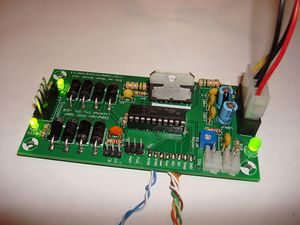
Connect Power to Board
Always turn your power supply off before plugging it in. It won't fry things most of the time... but all it takes is once to damage things.
Simply take your hacked PC power supply and plug a power connector into board. The green LED next to the connector should light up. If it doesn't, check its polarity and bust out your multimeter!
Turn your power supply off while you plug boards together!
Insert L297 chip
Turn the power off!!
Now that the power is off, it is time to insert the chip that tells the L298 when to turn on and off. Line up the semicircle on the chip with the semicircle on the silkscreen (and the chip socket if you did it right :) ) Make sure all the legs are properly in the socket, and fully insert it. You shouldn't need to remove it after this, so feel free to push it all the way in.
Now that your chip is fully inserted, turn the power back on. The LEDs next to the stepper header should also light up, as the stepper is enabled by default. If they both do, then chances are your circuit is working properly!
Give it a test drive.
Connect Board to Arduino.
This part is very easy. Strip 1/4" from the end of the input wires (You used Cat6 ethernet innards right???) Now, insert the end of each input into the correct pin on the Arduino, and then connect the Ground pin to Ground on Arduino. Use the table below to determine what pins to hook up to what:
| Board Pin | Arduino Pin |
| STEP | 4 |
| DIR | 5 |
| GND | Ground |
Upload Firmware to Arduino
Now, feel free to turn on the power to your power supply. Next, open the Arduino software, copy the code below into your sketch and upload it. After the firmware has compiled and uploaded, the Arduino will restart and the exerciser will begin shortly.
#define stepPin 4
#define dirPin 5

void setup() {
  Serial.begin(9600);
  Serial.println("Starting stepper exerciser.");

  pinMode(stepPin, OUTPUT);
  pinMode(dirPin, OUTPUT);

  digitalWrite(dirPin, HIGH);
  digitalWrite(stepPin, LOW);
}

void loop() {
  int i, j;

  for (i=1000; i>=200; i-=100) {
    Serial.print("Speed: ");
    Serial.println(i);

    for (j=0; j<2000; j++) {
      digitalWrite(stepPin, HIGH);
      delayMicroseconds(i);
      digitalWrite(stepPin, LOW);
      delayMicroseconds(i);
    }

    delay(500);
    digitalWrite(dirPin, !digitalRead(dirPin));

    for (j=0; j<2000; j++) {
      digitalWrite(stepPin, HIGH);
      delayMicroseconds(i);
      digitalWrite(stepPin, LOW);
      delayMicroseconds(i);
    }

    delay(1000);
    Serial.println("Switching directions.");
    digitalWrite(dirPin, !digitalRead(dirPin));
  }
}
The basic way the motor exerciser works is this:
- The stepper will take 2000 steps in one direction
- The stepper will take 2000 steps in the opposite direction
- The speed will increase or decrease.
The stepper exerciser will gradually increase/decrease the stepper motor to show a wide range of possible speeds and movements. It will do 2000 steps in each direction at each speed.
The higher speeds might be too high, your motor, although correctly connected, will just beep then.
You can easily visually verify that the stepper motor driver is working after you do this, as the LED's next to the stepper driver will light up with an orangeish color. This is because the LED's are switching from green to red very rapidly. If this is happening, then congratulations: your stepper driver board is a success!
<videoflash type="vimeo">419702|400|300</videoflash>
Hook up a stepper motor
You'll need a stepper motor to drive at this point.
Find a stepper motor that you have wired up to a .156" pitch connector. You can view wiring diagrams for various stepper motors if you have not wired any up yet.
Make sure the power to your driver board is off and insert the connector. Reset the Arduino board and turn the power on for your power supply. After a few seconds, your stepper motor should spring to life. When it does, do a little dance because you've just cleared the hardest hurdle in making a robot that can do some amazing things.
Troubleshooting
- First, check to see that you have supplied power to the board.
- If that doesn't work, check that you have the board wired up correctly to the Arduino.
- If the motor does not move at all, then check your circuit for shorts and dry joints.
- If the motor does not move, but is very jerky, then you have miswired the stepper to the board. Simply reverse the polarity on one coil to make it function properly. (eg. switch A with B)
Hacks!
Run off a single 12v supply

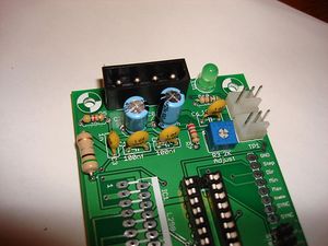
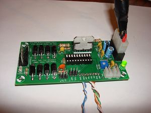
It is easy to adapt the stepper board so that it will run from a single 12v supply. The picture on the right shows a screw connector bringing in 12v (black stripe) and ground (white) wires. Under the screw connector, and inserted in the holes on the board before the connector was soldered in, is a 78L05 5v regulator. Its ground pin goes to one of the two central grounds. Under the board (and so invisible here) that pin is bent over and soldered to short the two central ground connectors together. The input to the 78L05 goes to the 12v input under the screw connector. The 5v output from the chip goes to the 5v input hole on the board.
That is all that is needed to run this board of a single 12v supply. Take care not to short the 12v line to ground by running the input to the 78L05 too near the ground connector.
The next generation of this board will have space for the 78L05. You will be able to choose to put that chip in, or replace it with a jumper and thus run the board off a (5v, 0v, 12v) supply as is the standard now.
Making a 0.5 Ohm 2 Watt Resistor
2 Watt 0.5 Ohm Resistors can be hard to get in some locations. Many stores don't stock 2W resistors, going from 1W to 5W - and the 5W are large beasts with thick wires. 0.5 Ohms is an unusual value for a resistor too. Fortunately, using two 1 Ohm 1 Watt resistors wired in parallel works just fine.
History
Changelog
- fatten ground wires!!!
- fatten all wires too
- make board bigger to accomdate
- extra mounting holes
- test/add pullup resistor on enable
- test/add pullup resistor on reset
- wire cntl directly to vcc
- combine two grounds
- wire reset directly to vcc
- fix silkscreen on min/max
- power-on LED indicator
- bicolor LED's on output (one per channel, color indicates polarity)
- remove unneeded jumpers
- add test point for trimpot
- remove unneeded input pins
Previous Versions
- An incremental improvement of the Stepper Motor Driver v1.0
- Which is a board to replace the Universal Controller v1.2