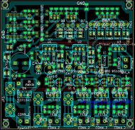
RDB-STP-001-G-DIY
Generic pages: | Introduction | Naming convention | TS Interfaces | Feature Interfaces | Steppers Interfaces | RDB_calibrations | RDB_DIY_tips |
Specific pages: | RDB-TS-001-G-DIY |
Release status: experimental
| Description | Generic development board extension for 3D printing
|
| License | |
| Author | |
| Contributors | |
| Based-on | |
| Categories | |
| CAD Models | |
| External Link |
Features Overview
This board is meant to take GPIO wires from the development board and provide support components for pololu stepper drivers.As the logic voltage regulator is continuously adjustable, the board can work at a logic voltage of 5v or 3.3v or else. Board features:
-Voltage regulator: 1 (adjustable)
-Headers to accomodate pololu drivers: 5
-Pcb size: two types of routing, 42x215mm (inline) and the other more compact 112x80mm
-optimized for DIY: single sided, no bridges, clearance 0.5mm, min track width 1.5mm, format and traces "bulky" enough so board could be made with any technique.
Power input
- simple reverse polarity protection with high current diode and fuse
- transient supressor
- max input voltage depends on the regulators used
Voltage regulator
- one continuously adjustable voltage regulator
- multiturn adjustment pots
- voltage regulator is 3 terminal type, TO-220 package, e.g.: LM317 LM1086, and similar pinout compatibility (TO220 with middle pin Vout)
- first regulator purposed for logic voltage for the board and should be set accordingly: 5v or 3.3v. Ideally this should be set to match closely the development board's logic voltage.
Source files
Schematic: download as PDF file
Kicad source files: download Kicad files - version 001a - last updated: 2013 May
