RAMPS 1.4.4
Version specific infoRAMPS 1.7 | RAMPS 1.6 | RAMPS 1.5 | RAMPS 1.4.4 | RAMPS 1.4 | RAMPS 1.3 | RAMPS 1.2 (RAMPS 1.2 old) and older
Release status: Prototype

| Description | RepRap Arduino Mega Pololu Shield
Arduino MEGA based modular RepRap electronics.
|
| License | |
| Author | |
| Contributors | |
| Based-on | |
| Categories | |
| CAD Models | |
| External Link |
Summary
A RAMPS board for a single 24V supply. Can be used with TMC2130 drivers, and controlled by both 8-bit and 32-bit controllers.
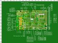
Board
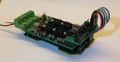
Test fitting on a Re-ARM

Click any image for larger versions
How this board came into existence
While I were designing the RAMPS 1.7 shield, a friend said: Well, that is all good and dandy, but 10x10 cm is too big for my printer. I need a RAMPS shield that can do TMC2130 drivers (without wire jumpers), be used with a single 24V power supply, and still be only the size of a standard RAMPS board, or it will not fit nicely on my printer.
So we came up with the following design framework:
- only a RAMPS 1.4 foot print (+/- a few millimeters if necessary)
- two additional fan ports. As this particular printer also needs a hot-end cooler fan (you know, for that extra fan on the E3D V6 hot-end that cools the heat breaker section of the hot-end), and a controller-board cooler-fan (because electronics that are trapped inside a very small controller enclosure tends to get too hot, with out at least some forced air movement.
- all TMC2130 SPI wires on the main PCB (preferably jumper selectable, so more ordinary stepper drivers can be used for Z-axes and the two extruder steppers).
- one 24V power supply only, to power everything.
- an integrated 12V DC-DC converter. To supply power to the Mega, and possibly 12V to the fans.
- works with the RRD LCD 4-line text display.
- preferably no polyfuses for the main power, but with everything still fused on the main board.
- integrated 100nF capacitors on the end-stops.
- SMD mosfets
- ability to be controlled by 5V and 3.3V controllers alike. Meaning:
- all mosfets will have a 5V buffer chip, in order to translate 3V MPU (main controller board) signals to 5V mosfet gate signals.
- having 5V available on the board (and the AUX-3 port), even if the MPU (main controller board) is mainly a 3V board.
We have since added:
- Hardware SPI port, (in the middle of the Arduino board) and not only from pins 50-52.
- a 12V Z-probe port-option.
- 4K7 ohm series-resistors on end-stops, so 3V MPUs can (hopefully) be 5V tolerant.
- 5V, 12V and 24V pins
Files
Once we have a working prototype, we will share the design files.
Schematics

PDF version here