R2C2 RepRap Electronics
Release status: working
| Description | New cutting edge electronic board for RepRap 3D printers
|
| License | |
| Author | [[User:[1]]]
|
| Contributors | |
| Based-on | [[]]
|
| Categories | |
| CAD Models | |
| External Link |
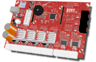
R2C2 electronic board works for RepRap 3D printers: Mendel; Prusa; Huxley. R2C2 also works for Rapman 3D printers. We expect this electronic board to be used with other 3D printers/lasers/CNC, etc.
If you are a user you can go directly to R2C2 Documentation page.
If you are a developer/hacker you can go directly to R2C2 Development page or to the github https://github.com/bitboxelectronics/ where you can find all the hardware (schematics), firmware and software.
Laser Open Source project - www.laoslaser.org mention this electronics/firmware as a candidate for their project. Peter Brier from LAOS have an R2C2 and is developing for it.
Contents
Important advantages
- Just one board, a complete solution, to control your RepRap 3D printer (can also control any other 3D printer/laser/milling);
- Plug and print - you will receive it completed assembled, tested, with proper versions of software and manuals on uSD card. No need to search on the web for the correct versions!
- High speed printing and quality due to the cutting edge technology 32 bits ARM microcontroller (version 1.2: LPC175x) running at 100MHz with fast integrated USB controller;
- Heated Bed support;
- uSDCard to store board configurations in human readable text files. In future it will also store files for standalone printing (no need to be connect to a computer computer);
- Buzzer to alert user of the different states of the 3D printing process, like end of machine heating, start and end of printing, etc;
- USB bootloader working as a USB Mass Storage device (works on Linux, Windows and MAC OS) - you will just need to copy/paste new firmwares to board as if is a USB pen flash;
- Expansion header to support other functionalities like a second extruder for support material, support a laser to engrave/cut paper, wood, ABS, PLA, etc;
- 24/12 volts power input. At 24 volts power losses on cables are lower providing faster heating making it quicker to start printing;
- All the firmware were developed with OpenSource development tools: ARM GCC, ARM GDB, OpenOCD JTAG Programmer/Debugger and Eclipse. We intend to continue developing firmware and expansion modules, for adding new features. We envision the R2C2 to became the "Arduino" of the RepRap world.
- Open Source: R2C2 source files of PCB, schematic and firmware are available on R2C2 Github account and so every user can take advantage and improve/adapt/hack R2C2 for his own purposes.
Specifications
| R2C2 V1.0 specifications | ' |
| Input power supply voltage | 12 to 24 volts |
| 1 orange LED to signal the power input | |
| Microcontroller | ARM 32 bits |
| Running at 100MHz | |
| 512 kbytes of flash memory | |
| 64 kbytes of SRAM memory | |
| USB 2.0 full-speed rate of 12 Mbit/s device, Host and OTG | |
| 8 DMA channels | |
| Stepper motor controllers | 4 stepper motors controllers for X, Y and Z axis plus E axis Extruder |
| 1/16 microstep for each axis | |
| Current control of each axis of up to 1.6 amps | |
| One red LED for each axis to show his activity | |
| Extruder | Mosfet without dissipator can drive a maximum of 4A(*) |
| The NTC temperature sensor circuit is optimized for temperature values range of 150 - 300 ºC with a precision of 0.25ºC | |
| 1 fan controller with variable speed. This controller can control up to a maximum of 75mA fan current. | |
| 1 red LEDs showing the activity on the heater | |
| Heated Bed | Mosfet with dissipator can drive a maximum of 9A(*). |
| The NTC temperature sensor circuit is optimized for temperature values range of 0 - 150 ºC with a precision of 0.25ºC | |
| 1 red LED showing the activity on the heater | |
| (*)Power Supply | The board can work between 24 and 12V, with a maximum source current of 9A at Ta=25ºC |
| It's always preferred use of 24V power supply, enabling less energy loss on cables leading to quicker element heating | |
| The maximum power drive capability will be 220W @ 24V or 110W @ 12V | |
| 1 orange LED light with the 3.3V | |
| Opto switchs | 3 opto switchs, one for each X, Y and Z axis |
| 3 green LEDs on the R2C2 board for showing the activity on the opto switches | |
| 3 green LEDs on each opto switch board for showing the activity on the opto switches | |
| Buzzer | 1 buzzer controlled with a PWM signal |
| MicroSD Card | 2Gbytes MicroSD Card wired on SPI BUS |
| DMA channel | |
| USB | ARM integrated USB controller at full-speed rate of 12 Mbit/s |
| DMA channel | |
| blue LED for signal USB successful connection (can also be used for any other functionality like debug) | |
| Buttons | 1 button for reseting the board |
| 1 button for USB bootloader that can be used for any other functionality after boot | |
| UART header | UART 3V3 header for connection of a FTDI cable like this one. |
| DMA channel | |
| JTAG | ARM's standard 2x10 pin JTAG male connector for firmware flashing and debug |
| Expansion Header | 21 IO pins that shares other functionalities as: |
| 2 PWM and CAPTURE, with 32 bits resolution | |
| 3 ADC with 12 bits resolution, 200 kHz maximum sampling rate, with DMA channel | |
| 1 DAC with 10 bits resolution, 1 MHz maximum update rate, with DMA channel | |
| 2 UART with 6.25 Mbit/s maximum data bit rate; with DMA channel | |
| 1 SPI with 50 Mbit/s maximum data bit rate; with DMA channel | |
| 1 Ethernet controller (need external Ethernet PHY) of 10 Mbit/s or 100 Mbit/s, with DMA channel | |
| USB pins for use on USB device, Host or OTG | |
| Power pins for +5V, +3V3 and +Vin (12 volts up to 24V) | |
Please see here for more.
Modules
This board will have an expansion header so modules can be added to add new functionalities (the same idea as Arduino shields). On next topic we talk about an application we have in mind.
Applications
Laser cutter and engraver
It will be possible to develop a module that control a laser diode of 1W (or less). We will be able to cut and engrave paper, plastic, wood, etc. See here the tests that Leonard have done:
<videoflash type="blip">AYKfxj4C</videoflash>
<videoflash type="blip">AYKfxkMC</videoflash>
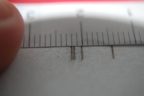
That cut was done with blue laser at 1W and with feed rate of F400 (6.6mm/s). The paper sheet had about 0.1mm.
We believe that we will be able to etch PCBs (like here) and make tracks/clearance of 0.25mm, for LQFP ICs of 0.5mm pitch :-)
Big thanks for Leonardo from Portugal to make this tests!
Circuit
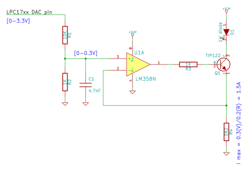
WARNING: This circuit is in development and test phase.

Source files for KiCad: File:Hbox-r2c2-laser controller.tar.bz2
Forum discussion
Electronic music for HBox RepRap electronics
R2C2 is shipped with (on the on board 2GBytes microSD Card) the sources files of RepRap 3D printers, R2C2 manual and sources, music, etc. The idea is to share data/files which we like (and are public, CC license, etc), just like Dead Drops project.
Here is an example of electronic, robotic and chip music shipped with R2C2 - please listen, download and share (Creative Commons license), this album from Norwegian artist Binary pilot. Music for you dance while your RepRap prints: <flickr>5194767568|left</flickr>

