Power Distribution and Communications Board v1.2
Contents
- 1 Depreciated! Use the Power and Communications Board v1.3 instead!
- 1.1 Power Distribution and Communications Board - v1.2
- 1.2 Overview
- 1.3 Build Board
- 1.4 Technical Stuff
- 1.5 Older Designs
- 1.6 Future Boards
Depreciated! Use the Power and Communications Board v1.3 instead!
Power Distribution and Communications Board - v1.2
Overview
<div class="thumb tright"></div>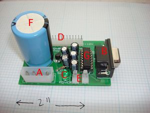
The Power Distribution and Communications Board consists of a hard drive style power input connector (A) that is the 12v supply for the whole RepRap machine, and an RS232 connector (B) that is the communications link to the computer controlling the machine. (C) is a power-on indicator LED. There is a row of six power output connectors at (D); these are wired into the other circuit boards in the RepRap machine to power them (only five are used for the Darwin design; the other is spare). The RS232 signals are converted to and from 5v TTL levels by the chip (G) and its associated capacitors. The data from (G) to and from RepRap's communications ring is sent and received by the connectors at (E). (F) is a large smoothing capacitor to keep the 12v supply clean.
- You'll need a soldering toolkit to do most of this.
- Read our Electronics Fabrication Guide if you're new.
- Refer to the bill of materials for information on parts.
Build Board
Oops! Board Bugs
v1.2.0
This was our first experience with ordering bulk PCB's. There were a couple mistakes. We've very sorry. None are a big deal, more like inconveniences.
Drill Holes
The biggest one, is that the mounting holes did not get drilled. There are 2 spots on each corner of the board where they were supposed to go, but did not actually get made. Drill those out with a 3mm (3/16") drill bit. If you do this before you build the boards, it will be easier.
Wrong Silkscreen
The silkscreen for the 4 pin power connector was rotated 180 degrees the wrong way. Follow the directions on this page carefully and you'll be fine. If you do manage to solder Berita Terbaru Berita Terkini Berita Hari Ini Berita Terupdate Kumpulan Berita Jasa SEO Murah Jasa SEO Baju Batik Toko Bunga it in the wrong way, its okay, but your board just won't work properly. If this happens, simply unsolder it, flip it around, and solder it back in.
v1.2.1
None so far. Please report any bugs in the forums.
Printed Circuit Board
<div class="thumb tright"></div>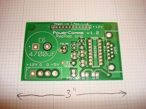
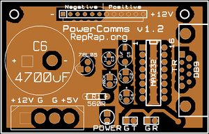
You can either buy this PCB from the RepRap Research Foundation, or you can make your own. The image above shows the professionally manufactured Power Communications v1.2 PCB ready for soldering. Its also cheap, only $5.00 USD.
File Locations
You can download the electronics files from Sourceforge. This zip file contains the Kicad files, as well as the GERBER files you can use to build it yourself (or have it manufactured).
If you'd like to make your own board, follow the v1.1 directions, as they use an older design (but identical/compatible) that is more suited to home manufacture.
Build Process
Soldering Round 1: Power
Solder in all the components except U2 and its four associated capacitors (C2...C5); that is, solder in all the components with red spots above. Solder in the lowest profile components first, then the higher ones. It will make it easier and the components will be more secure.
Recommended Order
- 16 pin DIP socket
- LED - polarity important. check silkscreen.
- resistor - any orientation
- 78L05 - match up flat side with silkscreen
- C1 (100uf) - polarity important. check silkscreen.
- 12 pin power connector - key/tab towards inside of board
- 2 pin signal connectors - key/tab towards inside of board
- 4 pin power connector - v1.2.1: follow silkscreen. v1.2: see bugs above.
- DB9 Serial connector
- C6 (4700uf) - polarity important. check silkscreen.
9-pin PCB D connectors come with a variety of ways of attaching them to the PCB in addition to the actual active pins. If you use our board and our supplier, the connector should just snap into place. Although different designs put the mountings in different places. If your connector coincides with those holes, all is well and good. But if it doesn't it may be simplest just to cut/saw-off the mountings and rely on the pins to hold the connector in place. This should be quite strong enough. Make sure you don't short any connections if you modify your connector.
Testing Round 1
<div class="thumb tright"></div>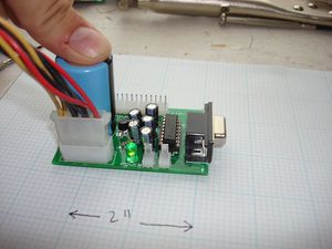
Plug a disk drive power connector from your power supply directly to the board. Turn the power supply on. Do not be surprised if there is a healthy crack and spark from the socket as you plug things in - the large capacitor takes a bit of filling up with electricity.
Check for smoke. The RepRap is a non-smoking area. If there's smoke, something went wrong.
Is there light? Check that the LED lights up. If it doesn't, you've made a mistake.
Proper voltages? Next put a voltmeter on the tracks that will connect to pins 15 and 16 of U2. This should measure 5v from the voltage regulator U1. If it doesn't, you've made another mistake.
Soldering Round 2: Communications
Disconnect the power.
Solder in C2...C5. Take particular care with the capacitors to get the polarity right - we designed it so all the capacitors face the same way. Negative should be towards you when holding the board so you can read the text on the silkscreen. The spacing of the holes for C5 is different than for C2, C3, and C4 (due to the straddling of a circuit). Simply bend the component legs apart a bit, then solder in normally. Finally, check it all again before you next apply power.
If you soldered in a DIP socket, then you simply plug U2 into that. Otherwise, solder U2 directly to the board.
Testing Round 2
<div class="thumb tright"></div>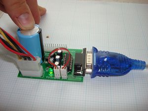
Plug your power back in and turn the power supply on.
Communications Test
A simple text communications program like minicom on Unix or Hyperterminal on Windows transmits data from the keyboard down the RS232 line. Data that comes back appears on the screen. This means that whatever the RS232 port is connected to normally has to echo what you type for it to appear on the screen.
This test shortcircuits that process by wiring the output straight back to the input. But they both go through U1, so that tests the communications part of the board.
Both the Transmit and Recieve connections also have a ground connection associated with them. These are not normally used; they are to allow us to use twisted pair data wires should the need arise later. The connections you want are the pins labeled T and R, the right of each pair. If you want, you can wire up a test connector that shorts them when you plug it into both.
Connect the card to the serial port of your computer. Then, short the transmit (T) and receive (R) lines that would normally go to the token ring. Now, check that a terminal program (like minicom or hyperterminal) echoes data to its screen when you type.
(In the finished RepRap machine T goes to the recieve input of the first RepRap control board - usually the X axis; R comes from the transmit output of the last RepRap control board - usually the support material extruder.)
Debugging your serial connection

Experienced hardware folk never trust their hardware. First make sure your serial port operates, which is easily done by shorting the Rx and Tx lines out on the serial lead from your PC. These are pins 2 & 3 and a small screwdriver will do the job. Do not touch the other pins or the casing. With the other arms, type characters at a dumb serial terminal such as Hyperterminal (Windows), minicom (Linux) or kermit (Linux) which has had all flow control turned off. If the port works, your typing should echo back - and stop echoing when you remove the screwdriver. If it doesn't work, you have the wrong port, a dead lead, a dead port, or if really unlucky a combination of the above. In linux the serial ports are referenced via ttyS0 (for COM1) and ttyS1 (for COM2), or ttyUSB0 (for usb <-> serial connectors. You can check which ports were detected by running one or more of the following:
find your tty device
look at the tty settings. use man stty to find out what each option means.
stty -F /dev/ttyS0
for my usb serial adaptor, i had to turn off imaxbel (beep and do not flush a full input buffer on a character)
stty -F /dev/ttyUSB0 imaxbel
When testing with comms software ensure flow control is set to "none". If in doubt for the other settings, use the following (though it's not too important at this stage): 19200 baud, 8 bits, no parity, one stop bit (8-N-1). If available, set carrier-detect to off.
Use the same principle to test the connector to the board, shorting it out with a screwdriver while no power is applied is acceptable. The pins to short are pins 2 and 3 of the serial connector on the module board (while the cable is still attached to the PC). If that doesn't work, your cable is suspect.
If all this checks out and you have verified the stripboard soldering, then you can apply power to the board. If you have a multimeter, check the following voltage levels are present. If any of these are wrong it suggests a defect in your wiring. In each case, measure from the first pin with the negative input of your voltmeter to the second pin with the positive input of your voltmeter. For these measurements, plug the power in, but do not plug the device into the PC. Also leave the communications connectors empty.
- Pin 15 to 16: 5V. A mismatch suggests a power supply or 7805 issue.
- Pin 15 to 14: -7 to -15V. A mismatch suggests a short on the board or a miswiring of the cable.
- Pin 15 to 13: 0V. A mismatch suggests a miswired cable.
- Pin 15 to 12: 5V
- Pin 15 to 11: 4 to 4.5V.
Now plug the serial connector into the PC (still leaving the communications connectors empty). You should now measure the following:
- Pin 15 to 16: 5V. A mismatch suggests a power supply or 7805 issue.
- Pin 15 to 14: -7 to -15V. A mismatch suggests a short on the board or a miswiring of the cable.
- Pin 15 to 13: -7 to -15V. A mismatch suggests a miswired cable.
- Pin 15 to 12: 5V
- Pin 15 to 11: 4 to 4.5V.
Now get a module connector cable (which is either 3 or 4 wires depending on how you're constructing your modules) and connect J2 to J3. This makes the comms card behave as if it is addressing other controller cards. Be sure that you don't get your cable twisted when you connect J2 to J3. Doing so shorts your 12V pin directly to ground, a move that is unlikely to do your power supply a lot of good.
Alternatively, you can simply attach a jumper wire from pin 1 on the outgoing comms connector (J2) to pin 1 on the incoming communications connector (J3). Take great care not to get your connector cable twisted.
You should now observe the following:
- Pin 15 to 11: 5V (rather than somewhere from 4 to 4.5V)
At this stage you should be able to do an internal echo test.
Using your comms software and the same settings as you previously used (no flow control), type or send some characters. The exact same characters should echo back to you. If you remove the power from the module, the echo should stop. Turn it on again and check that echo returns. Similarly, if you remove the comms cable echo should stop, put it back it and check that echo returns.
For Linux you can also use the 'poke' utility form the firmware toolkit to test the interface. I used device /dev/ttyUSB0 - a serial USB adaptor - as my serial port on a Linux box, Windows users probably have COM1 or something similar. Here is the command line; change your device to match and make sure you have access rights to that device (in Ubuntu you must be a member of the system dialout group):
It should come back with: <54><51><31><02><00><00><d0>[54][51][31][02][00][00][d0]Read fail 2 <54><51><31><02><00><00><d0>[54][51][31][02][00][00][d0]Read fail 2 <54><51><31><02><00><00><d0>[54][51][31][02][00][00][d0]Read fail 2 <54><51><31><02><00><00><d0>[54][51][31][02][00][00][d0]Read fail 2
If this does not happen, type:
stty -F $serialport -echo -cooked
and try again.
For Windows the poke utility is not currently available. You can use the Java stepper exerciser application instead. If you launch it and drag one of the position sliders, you should see the following error: Update exception: java.io.IOException: Received data packet when expecting ACK
Now you are ready to build and connect your stepper controller board.
More Debugging Instructions
Congratulations! You have finished your first RepRap circuit.
Technical Stuff
Circuit Diagram

Kicad Board Layout
Circuit Discussion
P1 is the main 12v power input connector - it uses a header that you can plug a standard PC power supply into. The 12v supply is taken straight through (via a big smoothing capacitor) to P4. These are the power distribution lines to the rest of the RepRap PCBs. There is one spare - you only need five for the Darwin design.
DB9 is a female PCB-mounting 9-pin RS232 socket. Serial data from your computer comes in here, is converted to TTL voltage levels by U2, and is fed out to the rest of the RepRap PCBs via P2 and P3. Remember that RepRap communicates using a token ring, so only two connectors are needed for data. U2 gets the 5v power it needs from U1.
Note that it has large ground and 12v planes on the board. This both saves etching chemicals and also handles the current needed by all the other RepRap boards.
Finally there is an indicator LED so you can remember when you've left your RepRap switched on...
Older Designs
- This design is based on the older, Power and Communications board v1.1
- Which is based on the older, stripboard comms controller designed by Simon.