MetalicaRap Photos and Drawings
MetalicaRap V3.00
File:Gun Coil Pump Cost calculator MetalicaRapReadOnly.ods This is MetalicaRap's master spreadsheet click on to download. Remember you can download the main assembly301 shown below and open it directly in freecad, from file and parts section.
MetalicaRap V. 3
MetalicaRap V. 3
MetalicaRap V. 3
MetalicaRap V. 3
MetalicaRap V. 3
MetalicaRap V. 3
MetalicaRap V. 3
MetalicaRap V. 3
MetalicaRap V. 3
MetalicaRap V. 3
MetalicaRap V. 3
MetalicaRap V. 3
MetalicaRap V. 3
MetalicaRap V. 3
MetalicaRap V. 3
MetalicaRap V. 3
MetalicaRap V. 3
MetalicaRap V. 3
MetalicaRap V. 3
MetalicaRap V. 3
MetalicaRap V. 3
MetalicaRap V. 3
MetalicaRap V. 3
MetalicaRap V. 3
MetalicaRap V. 3
MetalicaRap V. 3
- ..........................................
- Old illustrations
MetalicaRap V. 3
MetalicaRap V. 3


Version 2.0
File:MetalicaRap vers. 2.04.dwg
File:Assembly1 MetalicaRap V2.04.stl
Click on file names to download file
MetalicaRap V. 2
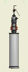
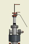
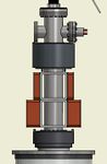
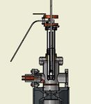
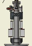
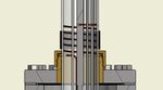
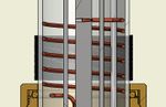
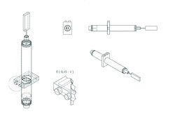
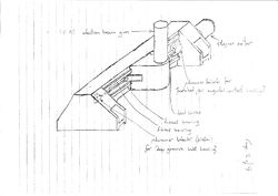
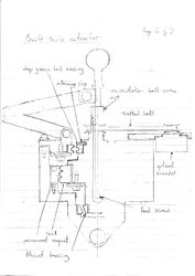
Gun & coil section side view 1:2 - File:Gun coil section side view MetalicaRap vers. 2.0.pdf
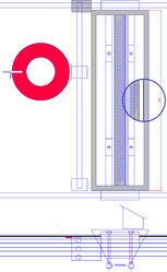
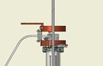
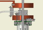
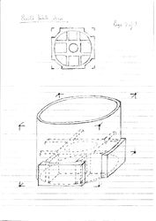
Hopper sense ring section side & plan view 1:2 - File:Hopper sense ring MetalicaRap v2.pdf
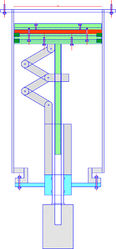
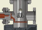
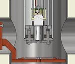
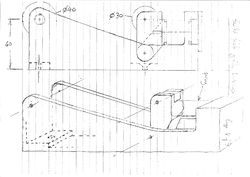
Build platform piston section side view 1:5 - File:Build platform MetalicaRap v2.pdf


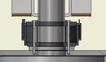
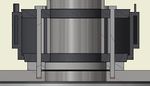
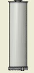
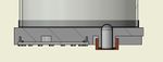
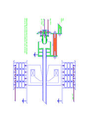
The 12Kg hopper is supported by a 2 linear bearings at opposite ends. In the Y sense ring motion direction the ring is supported by two linear bearing one above each other next to the red sense ring.The hopper (x axis) and ring (Y axis) are moved by a threaded axels, the drive force is only applied to one axel at a time and is switched by a splined axel. The splined axel is situated on one side of the 12Kg hopper above the other drive axel and linear bearing bar in the x direction. In the y direction their is no spline, just two linear bearings and a drive axel. This drive switching via the splined control rod switchs the motion /drive power between hopper deposition direction x and sensor ring drive direction y, by a further twist on the control spline in one of two directions releases powder deposition from one of 2 hoppers. In the x hopper deposition direction the spline will push a bi laminar slide shutter with 45 degree knifed edge vents open, releasing powder from 12 Kg hopper on to the build platform, by an opposite further twist on control spline in the sensor ring drive direction (y axis control), the spline will push the second bi laminar slide shutter with 45 degree knifed edge vents open releasing powder from the reservoir hopper down to the 12Kg hopper situated below, refilling the 12Kg hopper.
For high vacuum non window context this designs requires the further addition of a textured cylinder below bi laminar slide shutter and hopper side mechanical conveyor to overcome possible powder clogging in higher vacuums.
The wire prongs attached to the end of the sensor ring will be pulled through the beam by the XY drives , thereby sensing the beams energy cross section, which will be radioed back to Unified accelerator Library control system, enabling automatic adjustment of beam focus, beam strength, beam spot size, position adjustment. Hopper sense ring (in red) containing 6 PIN diode pickups for SEM in TOPO mode, (In the widow option version the build platform will rise up to 5mm below window between powder deposition sweeps and the sensor ring will be on its own carriage to slid through this 5mm gap , vision resolution will be significantly reduced due to the presence of argon gas. [1].
Version 1.0
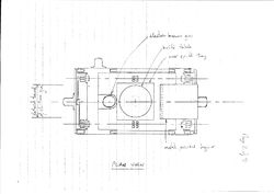
Plan view
Cartesian Gun A
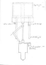
Side View build table
Plan view build table
Side Section of Build table actuator
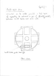
Build table drum
Build table guide bearings
Metal powder over spill tray , XY lead screw


. . . . . . Change of design priorities behind V2 MetalicaRap's redesign included; Single combined gun through finding existing examples of sub 10µ spot sizes from powerful guns, Cost of large box V.1 chamber, cost of high vacuum motors-exclusion of motors from inside chamber and introduction of motion feed throughs , rejection of UHV due to motion feedthroughs needing to be magnetic, use of ion pump, weight of single hopper, functionality of gravity hopper with correct powder fluidity and preparation, necessity for automated beam energy cross section diagnostics feedback to control system(UAL).