Lever Switch Endstops
This page describes how to use lever switches as endstops instead of optical sensors.
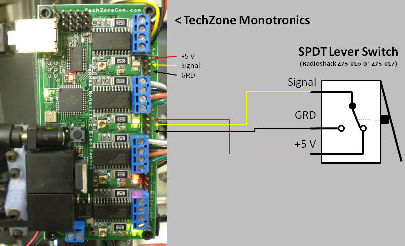
Caution: the following wiring schematic has been installed and tested with the TechZone Monotronics board shown in the picture. This method has not been tested with other boards. Check to make sure that the electrical operation of your board is similar to that of the Monotronics before connecting a switch.

- We decided to try this method on our units after we fried our umpteenth set of optical sensors by accidently placing the wires the wrong way. Using a lever switch as shown in the picture is particularly desireable for the X-axis as it is often hard to mount flags for the optical sensors. Also, it is nearly impossible to damage the switch or your board by swapping terminals by accident.
- When wired as shown above, the switch will apply +5V to the Signal input pin on the board when the switch is NOT compressed. When something makes contact with the lever and compresses the switch, the signal will be brough to ground (or approx 0V). Applying ground to the signal pin signals the stage to stop movement.
- It is important to note the location of the Signal pin on the board and on the switch, as they are not in the same order.
- A schematic of a Radioshack 270-016 or 270-017 (the 017 has a little wheel at the end of the lever) is shown in the picture. In fact, any SPDT swich can be used as long as the stage is able to trigger the switch.
| ||||||||||

