LaserCutXAxis
General
This page and its peers should guide you through assembling a RepRap Lasercut Mendel from the TechZone kit, or from parts you have laser cut which are the same as the TechZone parts. It is a work in progress, and needs some help, feel free to edit this document to add comments of you your own, or contact us [here] and send us messages asking us for better clarification or details.
I am starting by posting the pictures I have, and over the next few days, I will fill in the instructions and detials (6 April 2011)
Thanks,
Lambert (TechZone R&D/Support/Documenter)
You can access this page and it's peers (for the other parts of the Lasercut Mendel assembly from the TechZone Lasercut Mendel Page
Contents
Whene assembling the X Axis, assemble the parts just finger tight, and into aproximate areas. When it is all together, we will fix things by measurements, and tighten them up.
X Carriage
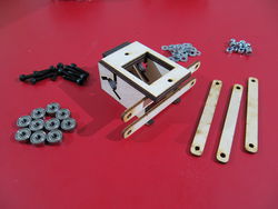
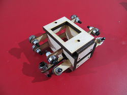
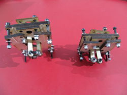
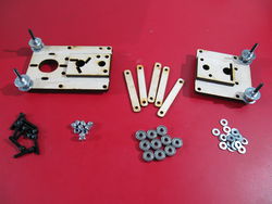
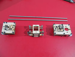
On the left is a picture of the parts used to make the X axis carriage (some people call it a shuttle) It is shown assembled on the right:
Start by attaching the bearings to one end of the 360 bearing spring arms. The stack goes bolt, washer, wood, one or two washers (depending on spacing needed to center on rod), bearing, washer, and nut. Slide the spring arms through the slots in the carriage on the 360 side aligning them so that each bearing will make contact with a rod running through the center. Attach bearings to the other side of the 360 spring arms with the same placement as the first end. Finally attach the bearings to the 180 spring arms with the bearings on the outside of the carriage.
Z180 and Z360 Degree X Axis Idler and Motor Mount
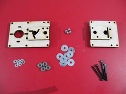
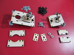
We use the parts shown on the left to make the assembly shown on the right.Start by attaching the bearings on the outside corners of the X idler and X motor mount. The stack goes bolt, washer, wood, fender washer, washer, bearing, washer, fender washer, nut. If the belt is too tight between the fender washers you can add an additional washer between the bearing and fender washer for extra space.
Next attach the bearing spring arms on the 360 and 180 side the same way as you did the carriage above.
Now you are ready to attach the smooth bar clamps and the Z nut retainer. Start by putting bolts through the X motor mount and X idler to their matching smooth bar clamps. The clamps with the notch go on the idler and the clamps with the round cut out go to the motor end. The nut retainers are the rectangular pieces with 4 smaller holes in the corners and a larger hole in the center. When you put the bolts through the clamp that also go through the nut retainer make sure you have the nut retainer in there as well. Leave it loose for now. Once that is done put the 8mm nuts in the spots for the nut retainer and tighten down the bolts on the nut retainer enough that the nut doesn't come out, but not all the way yet. Tighten everything else down most of the way, but make sure it is still loose enough that the smooth bars can slide in easily. The nut retainers have four holes so that they are symmetrical, but not all 4 holes need a bolt. Only the spots that have bolt holes on the motor and idler pieces need bolts.
Put them together
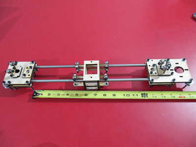
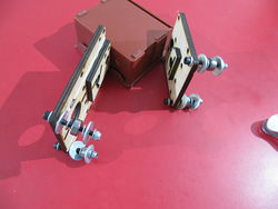
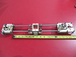
We use the parts we assembled above (shown on left) to complete the unit as shown on the right.
Put the idler end on your left and the motor end on your right with the carriage in the middle with the 360 side facing you. Slide the two smooth bars into the idler end until the ends of the bars are about to the end of the clamp. Tighten the bolts on the clamp down. Now put the carriage onto the smooth bars keeping the idler on your left and the 360 side of the carriage toward you still. Now slide the motor end onto the smooth bars till the bars are about to the end of the clamp. Tighten the bolts on the motor end clamp down enough that it will hold, but leave it loose enough you can still slide it on the smooth bars. we will tighten it down the rest of the way after we have it on the Z axis and have adjusted it to the correct length.
Squaring, and truing the size/shape
The squaring and truing of this axis is fairly simple. We want to make sure that the X Carriage 180 side has good contact between the bearings and the smooth bar. We want to make sure that the Z smooth bar will fit and ride in the 360 and the 180 sides without too much tension.
The X Carriage 180 is adjusted by means of the two bolts that hold the bottom bearing portion onto the main carriage. Simply loosen or tighten them as needed. There should be just enough tension for the bearings to make contact with the bar.
The Z 180 side is the easiest of the three, we don't check to make sure there is enough tension at this time, but we want to make sure ther is not TOO MUCH tension. The bar should fit between the bearings on the 180 end and should not rub on the plastic parts when it is "nearly" centered in the bearings.
The Z 360 side is the most temperamental. I often have to trim the shoulder between the straight bearing and the angled bearings. I trim it with a knife. The amount I have had to trim is very small when I have everything else adjusted well. The bar should go down through both sets of bearings and not rub on anything. If it is rubbing, I would first check to see that the parts are all fitting together as they should and the two 360 bearing clamps are parallel to each other. A common mistake here is to have the nut end of the bolts holding the 360 bearing and the Z nut retainer turned towards each other, rather than the heads of the bolts (take a close look at the pictures above, the nuts are on the outsides of the assembly, not the inside).
I have not posted pictures with this explainations, since I am not sure what to take pictures of to better describe the adjustments (other than the pictures in the steps above). If you have some please add them to this gallery... or send them to me and I will add them (see how to contact me above, I will send you my email address).
